
Piezoelectric power generator

a piezoelectric power generator and piezoelectric technology, applied in the direction of generators/motors, tyre parts, transportation and packaging, etc., can solve the problems of still existing output power of the power supply device, the development of a self-sufficient power generating device remains an unsettled question, etc., to prevent deformation, and increase the deformation range of the metal plate

Inactive Publication Date: 2011-06-16
ELECTRONICS & TELECOMM RES INST
View PDF7 Cites 47 Cited by
  • Summary
  • Abstract
  • Description
  • Claims
  • Application Information

AI Technical Summary

Benefits of technology

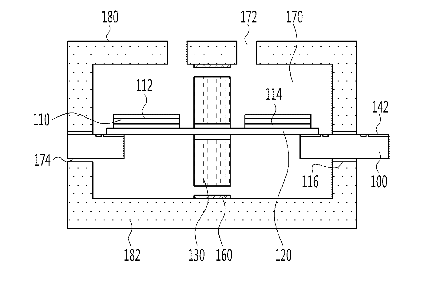
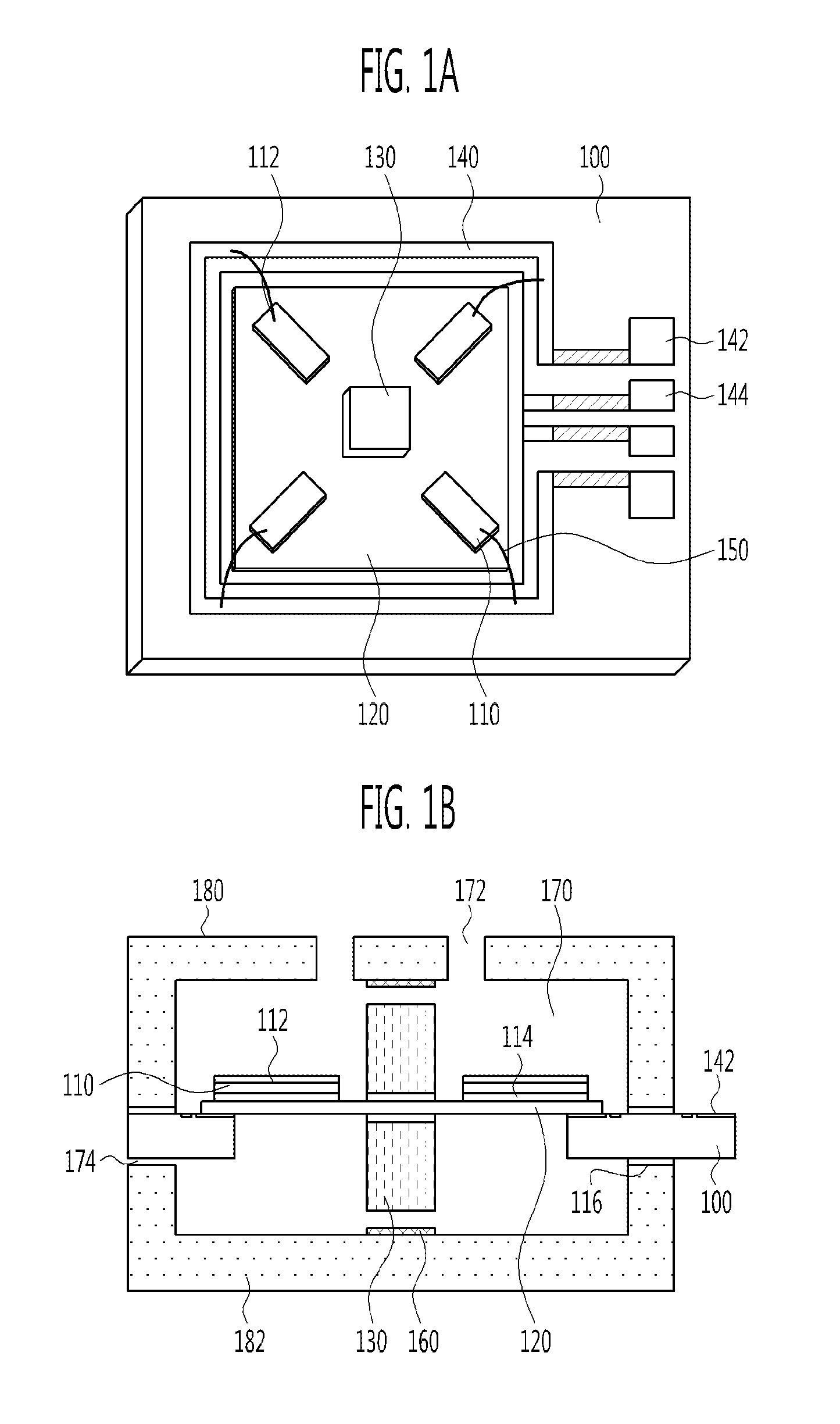
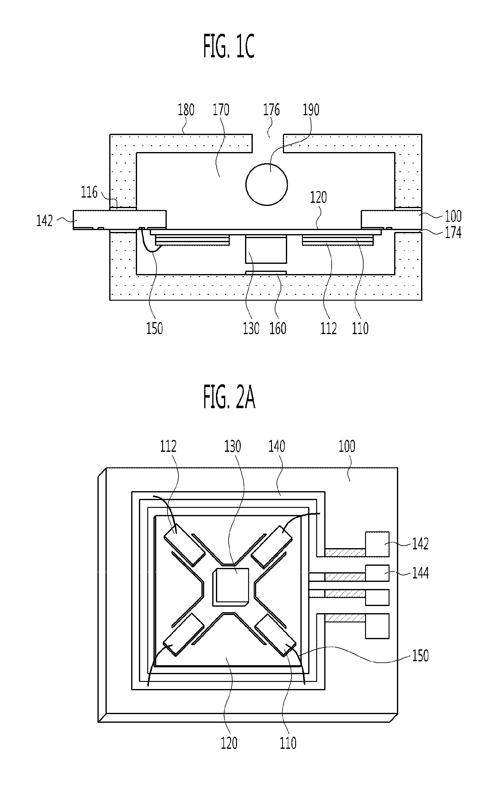
[0011]The piezoelectric power generator may further include a mass formed on the metal plate and increasing a deformation range of the metal plate when vibration is applied to the metal plate. The metal plate may have a bridge structure having a plurality of legs about the mass. The piezoelectric power generator may further include a housing connected to the substrate and surrounding the metal plate. The housing may include an upper housing surrounding an upper surface of the metal plate, and a lower housing surrounding a lower surface of the metal plate. The piezoelectric power generator may further include a mass formed on an upper or lower surface of the metal plate and increasing a deformation range of the metal plate when vibration is applied to the metal plate; and a stopper formed at the housing and limiting displacement of the mass to prevent deformation of t

Problems solved by technology

In operations of sensor or actuator modules in various environments, in order to drive the sensor module with no battery, development of a self-sufficient power generating device still remains as an unsettled question.
However, a problem with output power of the power supply device still exists.

Method used


Image

  • Piezoelectric power generator
  • Piezoelectric power generator
  • Piezoelectric power generator

Examples


Embodiment Construction

[0026]The present invention will now be described more fully hereinafter with reference to the accompanying drawings, in which preferred embodiments of the invention are shown. This invention may, however, be embodied in different forms and should not be construed as limited to the embodiments set forth herein. Rather, these embodiments are provided so that this disclosure will be thorough and complete, and will fully convey the scope of the invention to those skilled in the art. Like numbers refer to like elements throughout the specification.

[0027]FIGS. 1A to 1C show a TPMS structure in accordance with a first exemplary embodiment of the present invention.

[0028]FIG. 1A is a plan view of a piezoelectric power generator mounted on a metal plate having a membrane structure. Referring to FIG. 1A, a metal plate 120 having a membrane structure formed of an elastic alloy such as stainless steel, brass, or invar, is disposed on a printed circuit board (PCB) 100, on which a metal pattern 1...


PUM


Abstract

Provided is a small piezoelectric power generator applied to a wireless sensor network system of a tire pressure monitoring system (TPMS) for monitoring an internal environment of a tire such as variation in air pressure in the tire. In particular, when the system, in which air pressure, temperature and acceleration sensors are mounted, installed in the tire is operated in the TPMS for an automobile, a small piezoelectric power generator for the TPMS can be used as a power source in place of a conventional battery. The piezoelectric power generator includes a substrate having an electrode for transmitting power to the exterior, a metal plate formed on the substrate, and a piezoelectric body disposed on the metal plate and transmitting the power generated by a piezoelectric material to the electrode.

Description

CROSS-REFERENCE TO RELATED APPLICATION[0001]This application claims the benefit of Korean Patent Application No. 10-2009-0122962, filed Dec. 11, 2009, the disclosure of which is hereby incorporated herein by reference in its entirety.BACKGROUND[0002]1. Field of the Invention[0003]The present invention relates to a small piezoelectric power generator, and more particularly, to a piezoelectric power generator installed at a tire of an automobile to generate power using vibration and variation in air pressure of the tire.[0004]2. Discussion of Related Art[0005]Tire pressure monitoring system (TPMS) for automobiles is system for checking a tire status to support a driver in safely driving his / her car. In recent times, a system in which the TPMS is constituted by a wireless sensor network and a TPMS module is installed at a tire to communicate with the system in real time has been proposed. Therefore, the necessities of research on micro electro mechanical system (MEMS) devices having va...

Claims


Application Information

Patent Timeline
IPC IPC(8): H02N2/18
CPCB60C23/0411H02N2/186H10N30/306H10N30/308H02N2/00H02N2/02
Inventor KO, SANG CHOONJE, CHANG HANRYU, HO JUNLEE, SUNG SIKJUN, CHI HOON
Owner ELECTRONICS & TELECOMM RES INST
Learn More