
A high stability high pressure fire pump

A high-stability, fire-fighting pump technology, applied to pumps, parts of pumping devices for elastic fluids, pump components, etc., can solve problems such as reduction, reduce cumbersomeness, increase contact area, and reduce potential safety hazards Effect

Active Publication Date: 2021-03-16
沧州凯鼎机械设备有限公司
View PDF9 Cites 0 Cited by
  • Summary
  • Abstract
  • Description
  • Claims
  • Application Information

AI Technical Summary

Problems solved by technology

[0005] Aiming at the problems existing in the prior art, the object of the present invention is to provide a high-stability high-pressure fire pump, which, through the setting of the serrated snap ring and the wedge-shaped inner ring, inserts the water pipe between the mounting plate and the serrated snap ring on the one hand The installation can be completed within a certain gap. Compared with the installation of clamps in the prior art, the cumbersomeness of installation is significantly reduced, which effectively saves more time for fire fighting. The binding force becomes stronger and stronger with the increase of water pressure, so as to effectively avoid the occurrence of loosening or falling off of the water pipe during the fire extinguishing process, and significantly reduce safety hazards. When the deformation of the corner of the sawtooth clasp is too large, the embedded semi-brittle strip will break, and the water will flow out, making the undulating fixed layer and the undulating dynamic layer have super stickiness, and the water pipe will be bonded and fixed on the installation plate between the sawtooth clasp breaks , effectively prevent the water pipe from falling off during the fire fighting process

Method used


Image

  • A high stability high pressure fire pump
  • A high stability high pressure fire pump
  • A high stability high pressure fire pump

Examples


Embodiment 1

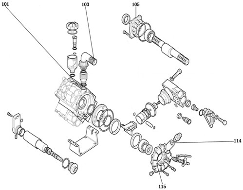
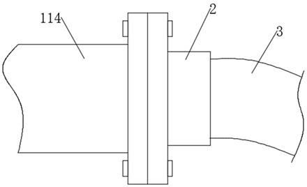
[0040] see figure 1 , a high-stability high-pressure fire pump, including a front cover 105, a pump casing 101, a drive mechanism, a booster mechanism, and a water outlet pool 115, the outer end of the water outlet pool 115 is fixedly connected to a water outlet 114, and the water outlet of the water outlet 114 Bolted with mounting disc 2 .

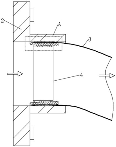
[0041] see Figure 2-4 , the end of the mounting plate 2 away from the water outlet 114 is provided with a water pipe 3, the inner wall of the mounting plate 2 is fixedly connected with a sawtooth snap ring 5, and the inside of the serrated snap ring 5 is fitted with a wedge-shaped embedded ring 4, and the inner wall of the installation plate 2 and the serrated snap ring The ends of the rings 5 ​​that are close to each other are respectively provided with an undulating fixed layer 61 and an undulating dynamic layer 62. The undulating fixed layer 61 and the undulating dynamic layer 62 are matched with each other, and the two are not in co...


PUM


Abstract

The invention discloses a high-stability high-pressure fire pump, and belongs to the field of high-pressure pumps. Through the high-stability high-pressure fire pump, through arrangement of a sawtoothsnap ring and a wedge-shaped embedded ring, on one hand, a water pipe is inserted into a gap between a mounting plate and the sawtooth snap ring, so that mounting is finished, compared with hoop mounting in the prior art, the mounting complexity is remarkably reduced, and much time is effectively saved for fire extinguishing; on the other hand, the binding force of the sawtooth snap ring and themounting plate to the water pipe is stronger and stronger along with the increase of the water pressure, so that the situation that the water pipe loosens or falls off in the fire extinguishing process is effectively avoided, the potential safety hazard is obviously reduced, and under the arrangement of an embedded semi-brittle strip and outer supporting pipes, when the deformation at the corner of the sawtooth snap ring is too large, the embedded semi-brittle strip breaks, and the water flows out, so that a fluctuation fixed layer and a fluctuation movable layer have ultra-strong viscosity, the water pipe is bonded and fixed on the mounting plate between the breakage parts of the sawtooth snap ring, and the water pipe is effectively prevented from falling off in the fire extinguishing process.

Description

technical field [0001] The invention relates to the field of high-pressure pumps, more specifically, to a high-stability high-pressure fire pump. Background technique [0002] As the name implies, the fire pump is a pump used in fire protection. The fire pump is an imported product. It is divided into different types according to different classification methods. It is widely used in environmental protection, water treatment, and fire protection due to its characteristics of full sealing, no leakage, and corrosion resistance. It is used to pump all kinds of liquids, and it is an ideal pump and fire protection system for creating non-leakage, non-pollution civilized workshops and civilized factories. The pump types are similar, but the head and flow are different. The selection basis of the fire pump should be considered according to the process flow, water supply and drainage requirements, and other five aspects. [0003] When a forest fire or a fire in a residential build...

Claims


Application Information

Patent Timeline
Patent Type & Authority Patents(China)
IPC IPC(8): F04D29/62F04D29/44F04D29/66F04D29/08F04D29/00
CPCF04D29/007F04D29/086F04D29/445F04D29/628F04D29/669
Inventor 王玉臣吴凤娟
Owner 沧州凯鼎机械设备有限公司
Learn More