Rotary seal with supported inlet

Active Publication Date: 2011-06-16
KALSI ENG
View PDF24 Cites 16 Cited by
  • Summary
  • Abstract
  • Description
  • Claims
  • Application Information

AI Technical Summary

Benefits of technology

[0013]An aspect of the present invention is to provide a simple and compact rotary sealing arrangement for containing a pressurized media such as oilfield drilling fluid, where the rotary seals employ the advantage of maintaining a film of lubricant at the dynamic sealing interface during rotary operation, without requiring the undesirable complexity of a wavy backup ring, and without the undesirable complexity of maintaining the lubricant at a pressure that is greater than the pressure of the pressurized media. Hydrodynamic geometry on a dynamic sealing lip interacts with a lubricating media during relative rotation to wedge a lubricating film into the dynamic sealing interface between the seal and the relatively rotatable surface. The lubricating film is distributed across the dynamic sealing interface and migrates toward, and into, the pressurized fluid, and thus provides a contaminant flushing action. The lubricating film reduces seal running torque, providing reduced wear and reduced seal-generated heat. In other words, the dynamic sealing lip slips or hydroplanes on a film of lubricating fluid during periods of relative rotation between the dynamic sealing lip and relatively rotatable surface. When relative rotation stops, the hydroplaning activity stops, and a static sealing relationship is re-established between dynamic sealing lip and relatively rotatable surface.
[0014]One feature of the present invention is a hydrodynamic inlet that is supported by one or more adjacent boundaries, such as a recess support corner, a first recess end and / or a support shoulder, in order to resist differential pressure-induced inlet collapse, so as to retain the hydrodynamic wedging function of the hydrodynamic inlet despite the high differential pressure acting across the rotary seal.
[0016]The shelf-like shape or shapes prevent the slots / recesses from collapsing completely against the shaft when the pressure of the contained fluid is higher than that of the seal lubricant. The lubricant is swept into the dynamic interface between the dynamic sealing surface and the washpipe, at the location near the extrusion gap where it is needed most for interfacial lubrication. A shelf-like shape also creates an angled zone of locally increased interfacial contact pressure that diverts lubricant film toward the environment-side edge of the dynamic sealing surface.
[0018]An optional feature of the present invention is the compression of a portion of a static sealing rim between a first sealing housing component and a second sealing housing component to establish a static sealed relationship between the first and second sealing housing components, and to prevent rotation of the seal / packing relative to the first and second seal housing components.

Problems solved by technology

While this type of packing has served the oilfield for many years, it is not suitable for the higher speeds and pressures of today's deep wells.

Method used


Image

  • Rotary seal with supported inlet
  • Rotary seal with supported inlet
  • Rotary seal with supported inlet

Examples


Embodiment Construction

FIGS. 1A-1D

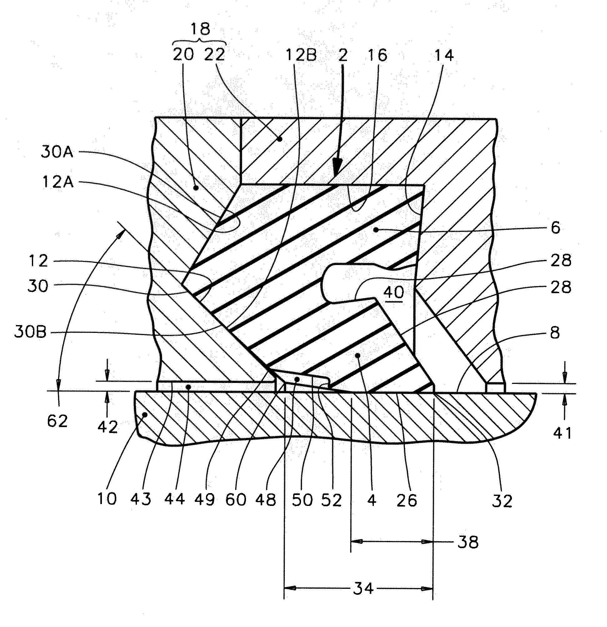
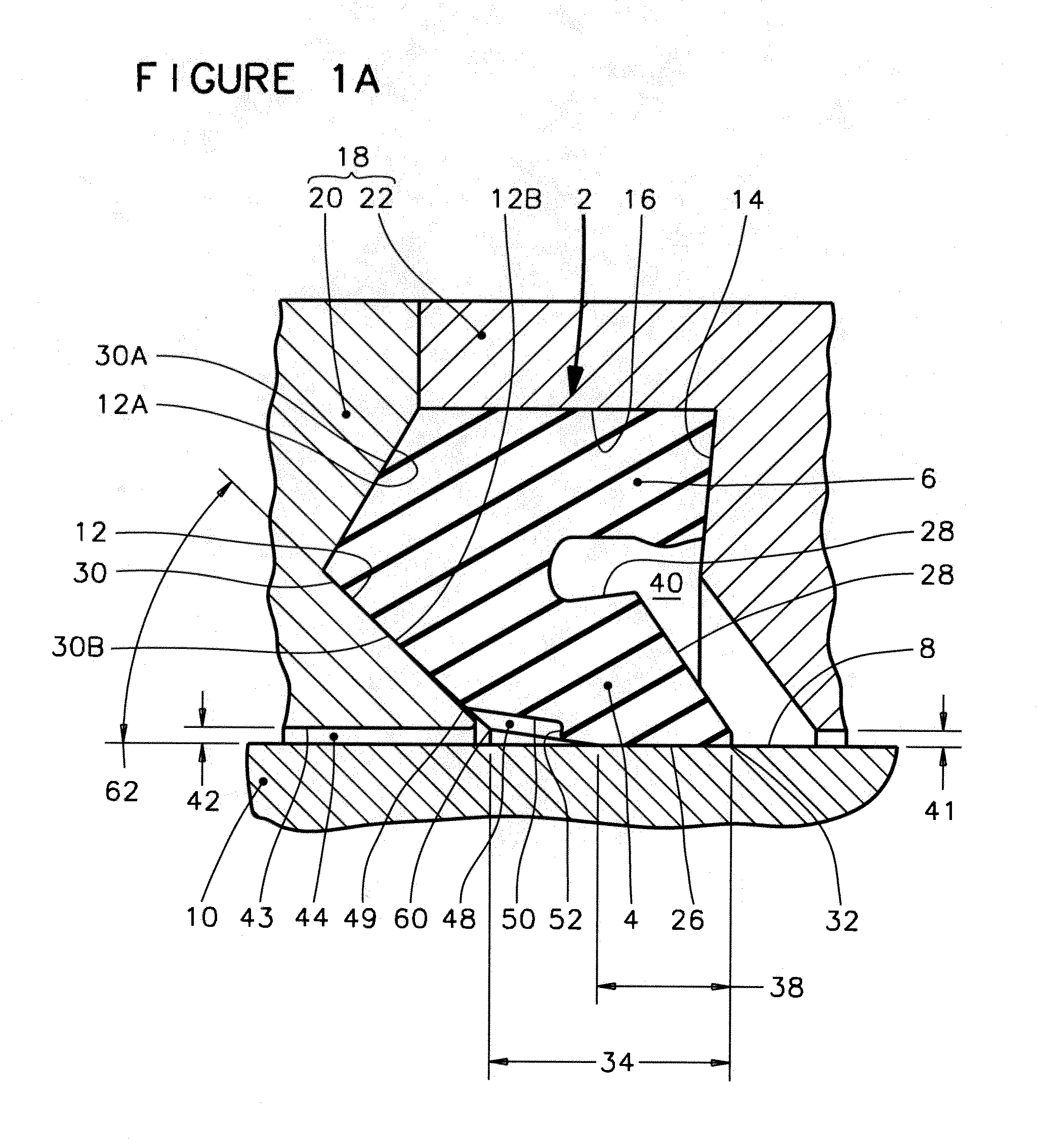
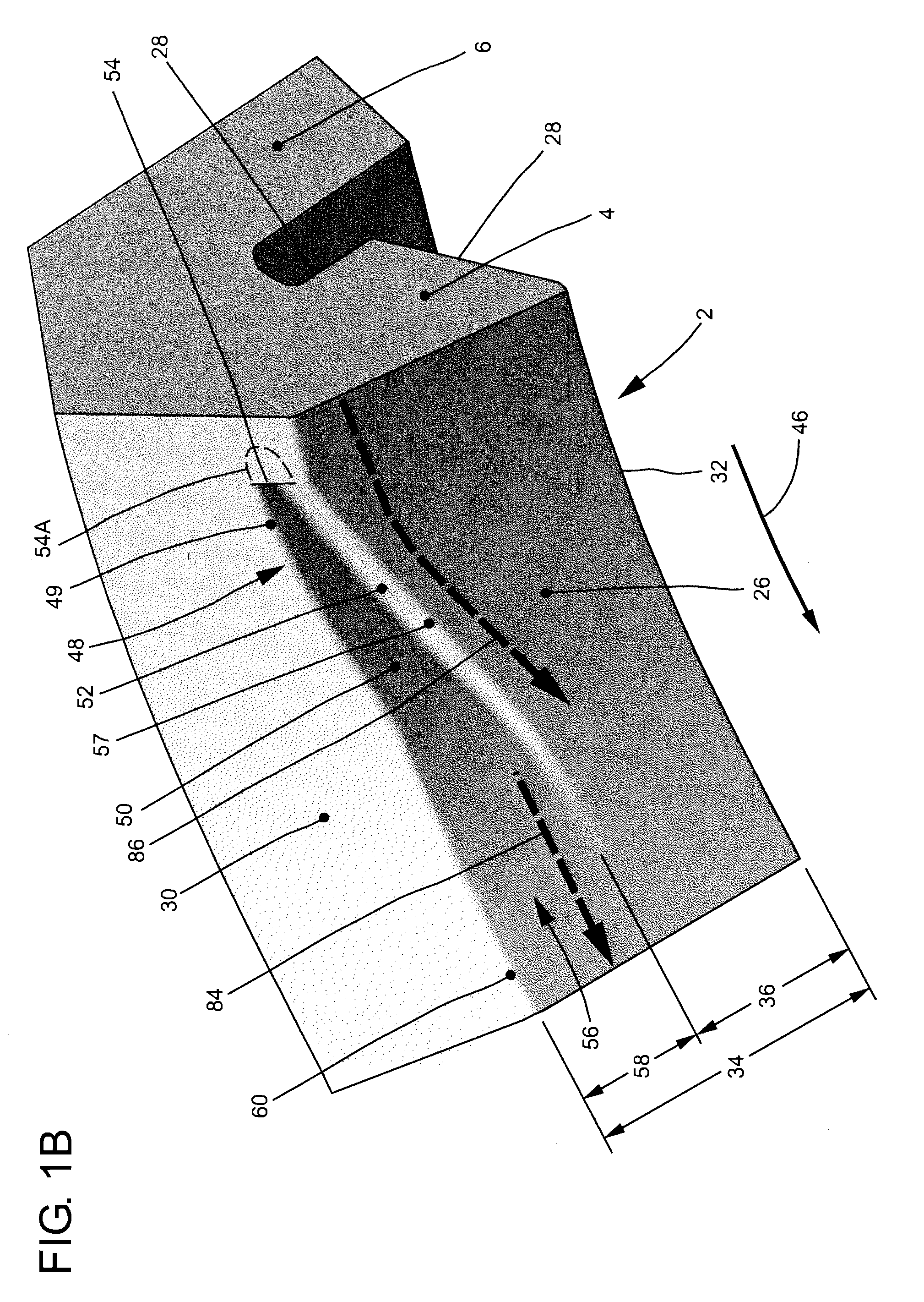
[0029]FIGS. 1A, 1B 1C and 1D are views representing one preferred embodiment of the present invention, and should be studied together, in order to attain a more complete understanding of the invention. Features throughout this specification that are represented by like numbers have the same function. While the invention is readily adaptable to various sealing configurations, FIGS. 1A-1D illustrate the invention in the context of an oilfield washpipe packing-type seal, and disclose how to achieve hydrodynamic interfacial lubrication using a novel collapse-resistant hydrodynamic inlet geometry.

[0030]The rotary seal of a preferred embodiment of the present invention is illustrated generally at 2 in its installed condition, in the absence of differential pressure in FIG. 1A, and FIG. 1C illustrates the rotary seal 2 in its installed condition in the presence of differential pressure. FIGS. 1B and 1D show two different perspective views of the rotary seal 2 in its uninstalled,...


PUM


Abstract

A hydrodynamically lubricated sealing element for applications where the pressure of a contained fluid can be significantly greater than the pressure of the seal lubricant. The sealing element retains the pressure of the contained fluid and provides hydrodynamic lubricant pumping activity at the dynamic sealing interface to enhance service life. The invention is particularly suitable for oilfield drilling swivel washpipe assemblies, downhole drilling tools, and rotary mining equipment, and for applications such as artificial lift pump stuffing box assemblies and centrifugal pumps where a rotating shaft penetrates a pressurized reservoir that is filled with abrasive-laden liquids, mixtures, or slurries.

Description

CROSS-REFERENCE TO RELATED APPLICATIONS[0001]This application claims the benefit of U.S. Provisional Patent Appln. No. 61 / 268,698 filed Jun. 15, 2009, entitled “Hydrodynamic Washpipe Packing Ring.” U.S. Provisional Patent Appln. No. 61 / 268,698 is hereby incorporated by reference herein.BACKGROUND OF THE INVENTION[0002]1. Field of the Invention[0003]This invention relates generally to seals that are suitable for containing a pressurized fluid that may be abrasive, and for providing a film of lubricant at the dynamic sealing interface in response to relative rotation to enhance pressure and rotary speed capabilities.[0004]The seals of the present invention are particularly suitable for use in rotary swivel assemblies, such as the general type of oilfield washpipe assemblies that are described in U.S. Pat. No. 2,764,428 entitled “Wash Pipe Mounting For Swivels,” IADC / SPE Paper 59107 “A New Hydrodynamic Washpipe Sealing System Extends Performance Envelope and Provides Economic Benefit,”...

Claims


Application Information

Patent Timeline
IPC IPC(8): E21B33/10
CPCF16J15/164F16J15/3244F16J15/3236E21B33/085
Inventor DIETLE, LANNIE LAROYGOBELI, JEFFREY D.
Owner KALSI ENG
Why Eureka
Try Eureka