
Linear compensation method of touch panel

Inactive Publication Date: 2011-06-09
GETAC TECH CORP
View PDF3 Cites 26 Cited by
  • Summary
  • Abstract
  • Description
  • Claims
  • Application Information

AI Technical Summary

Benefits of technology

[0009]In order to solve the problem in the prior art that the precision of a touch panel is easily influenced by temperature such that a user needs to continuously perform calibration as the temperature varies so as to eliminate the error, the present invention is directed to a linear compensation method of a touch panel which is applicable to a touch control computer system. Thereby, the touch control computer system implementing the method is capable of correcting errors caused by the temperature itself based on temperature variations without requiring the user to perform re-calibration as the temperature varies.

Problems solved by technology

The aforementioned processes always damage the uniform distribution of the transparent conductive film, such that the actual surface resistance varies and cannot match with the actual touch position.
For example, when a touch pen is used to contact the touch panel, a linear error is generated between a point of the touch pen and a position of a cursor when the cursor is moved to be below the point of the touch pen.
For the resistive touch panel, environmental factors, especially temperature, seriously influence the actual surface resistance.
As a result, the original reference surface resistance acquired at 20° C. is no longer applicable, and the user must perform the multi-point calibration procedure again to generate a new reference surface resistance.
However, for ordinary users, it is difficult to determine at what temperature difference the re-calibration is needed, and the re-calibration from time to time also brings inconvenience to the use of a touch computer device.

Method used


Image

  • Linear compensation method of touch panel
  • Linear compensation method of touch panel
  • Linear compensation method of touch panel

Examples


Embodiment Construction

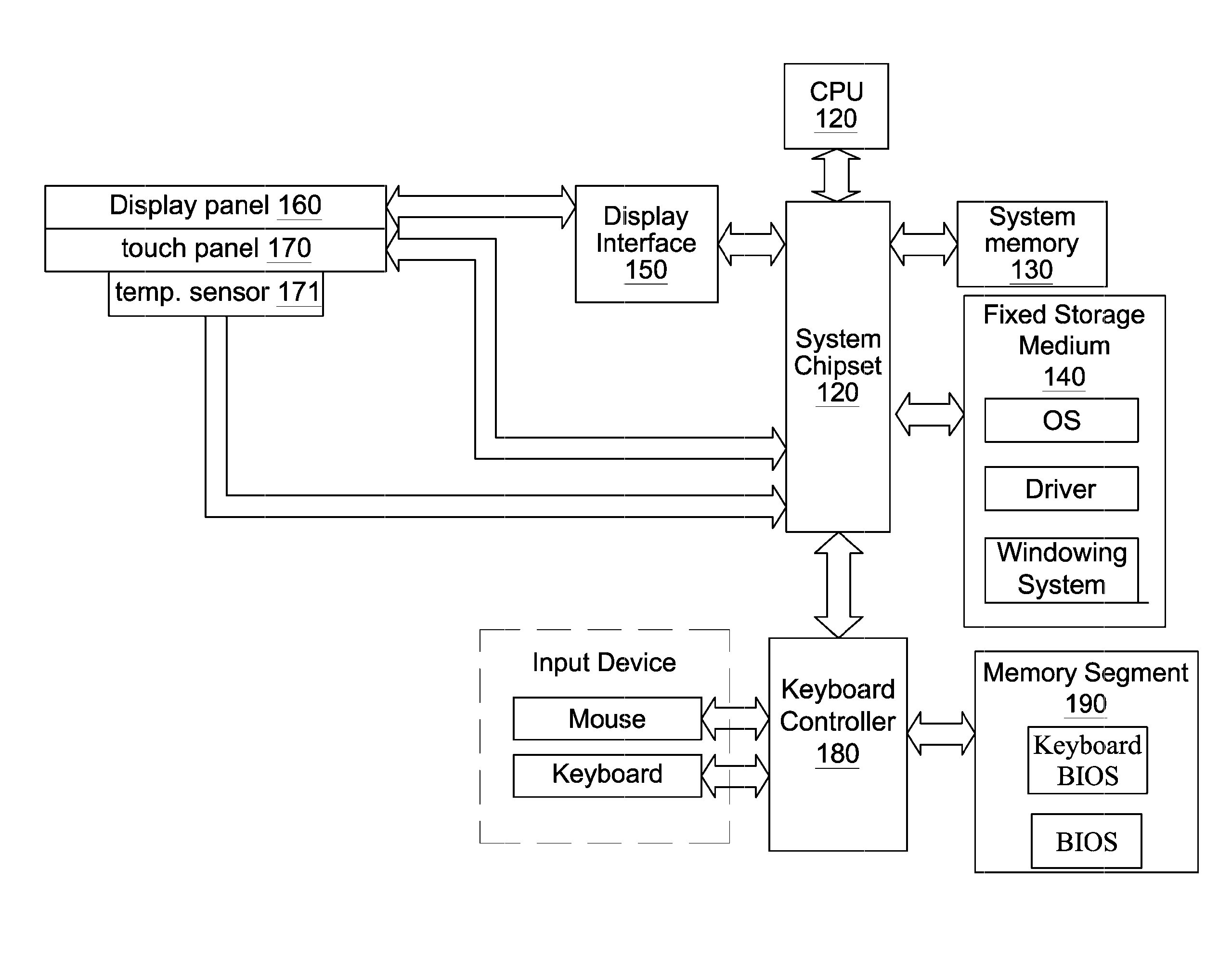
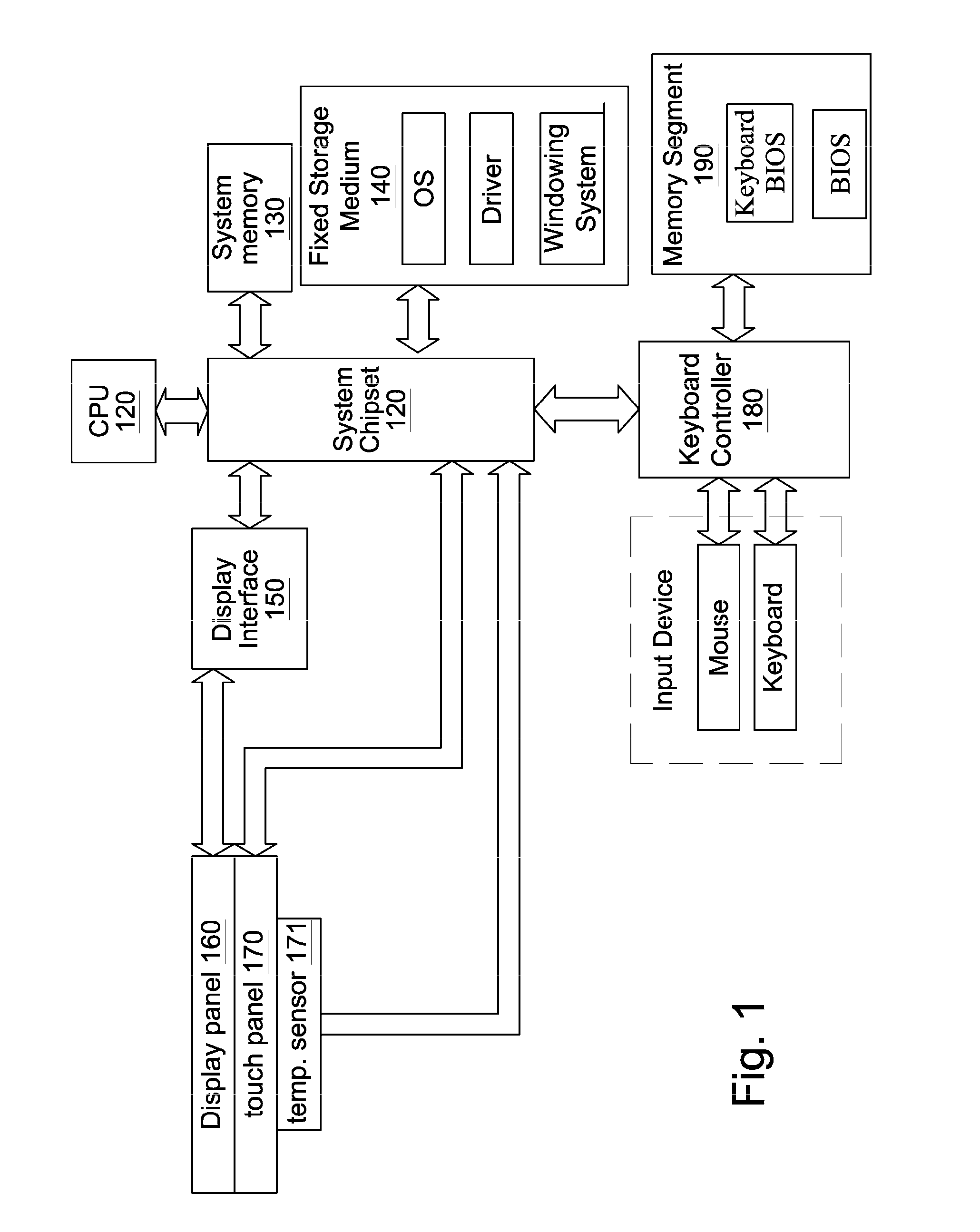
[0021]FIG. 1 shows a touch control computer system applying a linear compensation method of a touch panel according to an embodiment of the present invention. The touch control computer system includes a system chipset 110, a central processing unit 120 (CPU 120), a system memory 130, a fixed storage medium 140, a display interface 150, a touch display device, a thermal sensor 171, a keyboard controller 180, and a basic input / output system memory 190 (BIOS memory 190).

[0022]The touch display device includes a display module 160 and a touch panel 170 located on a front side face of the display module 160.

[0023]The system chipset 110 includes a south bridge chip and a north bridge chip for providing a bus to process data transmission between the elements. The CPU 120, the system memory 130, the fixed storage medium 140, the display interface 150, the display module 160, the touch panel 170, the thermal sensor 171, and the keyboard controller 180 are electrically connected to the syste...


PUM


Abstract

A linear compensation method of a touch panel is utilized to a touch control computer system. According to the method, a compensation reference table, including reference temperatures and reference surface resistances at pre-determined reference points having known coordinates at the reference temperatures, is obtained at first. Then, a set of user calibration resistance at the pre-determined reference points is obtained through a user calibration process, so as to obtain ratios of the user calibration resistances to interpolation surface resistances as correction weights. Under different temperature, interpolation surface resistances corrected by utilizing the correction weight to derive the current correction surface resistances that are corrected and nearly identical to actual surface resistances. Therefore, relatively precise coordinates are obtained through resistance-coordinate conversion process.

Description

BACKGROUND OF THE INVENTION[0001]1. Technical Field[0002]The present invention relates to linear error compensation of a touch panel, and more particularly to a linear compensation method of a touch panel that enables a touch control computer system to correct errors caused by the variation of the temperature itself.[0003]2. Related Art[0004]A touch control display has a touch panel combined with a display panel. The touch control panel allows a user to directly touch an icon or a menu displayed on the display panel so as to rapidly operate a computer system. In fact, the user touches the touch panel disposed on the display panel, and the touch panel feeds back a positioning signal to the computer system, such that the computer system converts the positioning signal to a coordinate value and then maps the coordinate value to an image displayed by the display panel.[0005]The categories of touch panels include resistive touch panels, capacitive touch panels, electromagnetic touch pane...

Claims


Application Information

Patent Timeline
IPC IPC(8): G06F3/045G06F3/041
CPCG06F3/045G06F3/0418
Inventor SHEN, CHANG-HAN
Owner GETAC TECH CORP
Learn More