
Disposable motor-driven loading unit for use with a surgical cutting and stapling apparatus

Active Publication Date: 2011-06-09
CILAG GMBH INTERNATIONAL
View PDF101 Cites 238 Cited by
  • Summary
  • Abstract
  • Description
  • Claims
  • Application Information

AI Technical Summary

Problems solved by technology

Such prior disposable loading units, however, require the clinician to continuously ratchet the handle to fire the staples and cut the tissue.

Method used


Image

  • Disposable motor-driven loading unit for use with a surgical cutting and stapling apparatus
  • Disposable motor-driven loading unit for use with a surgical cutting and stapling apparatus
  • Disposable motor-driven loading unit for use with a surgical cutting and stapling apparatus

Examples


Embodiment Construction

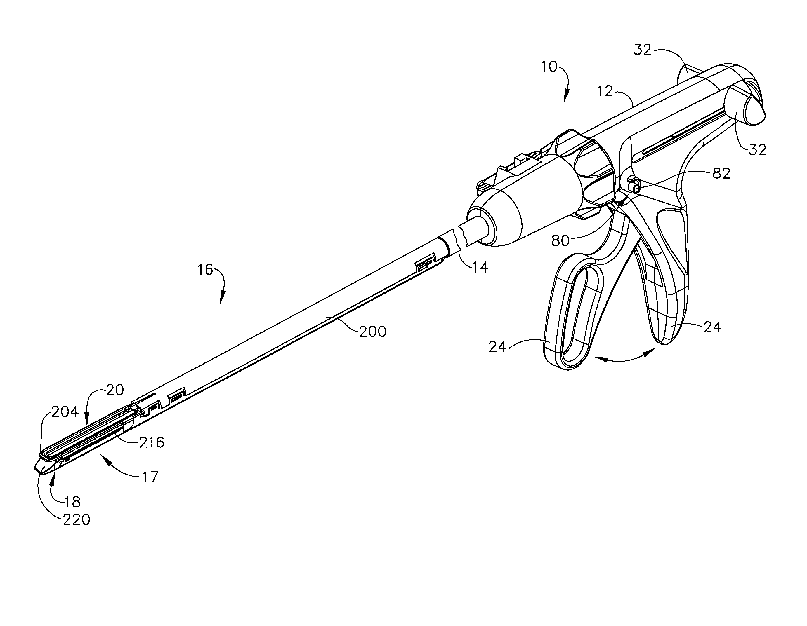
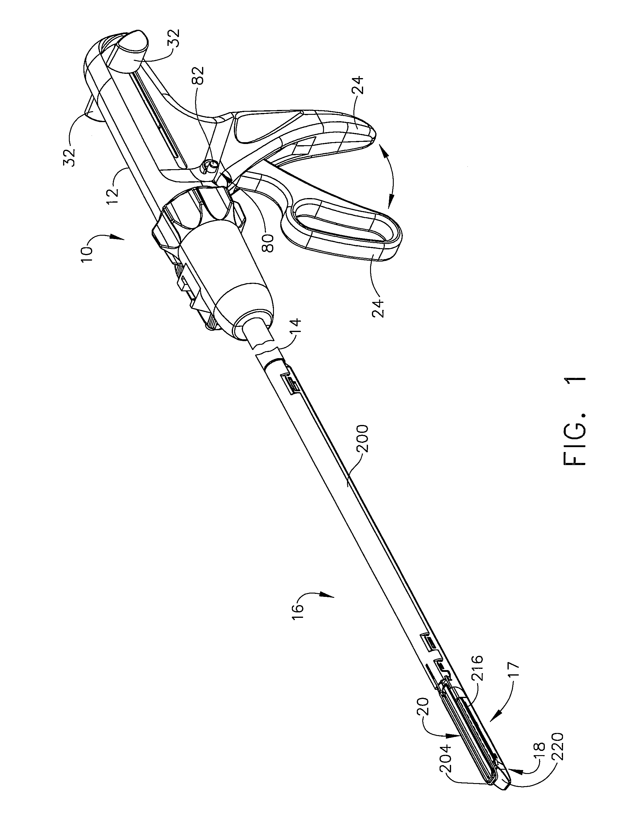
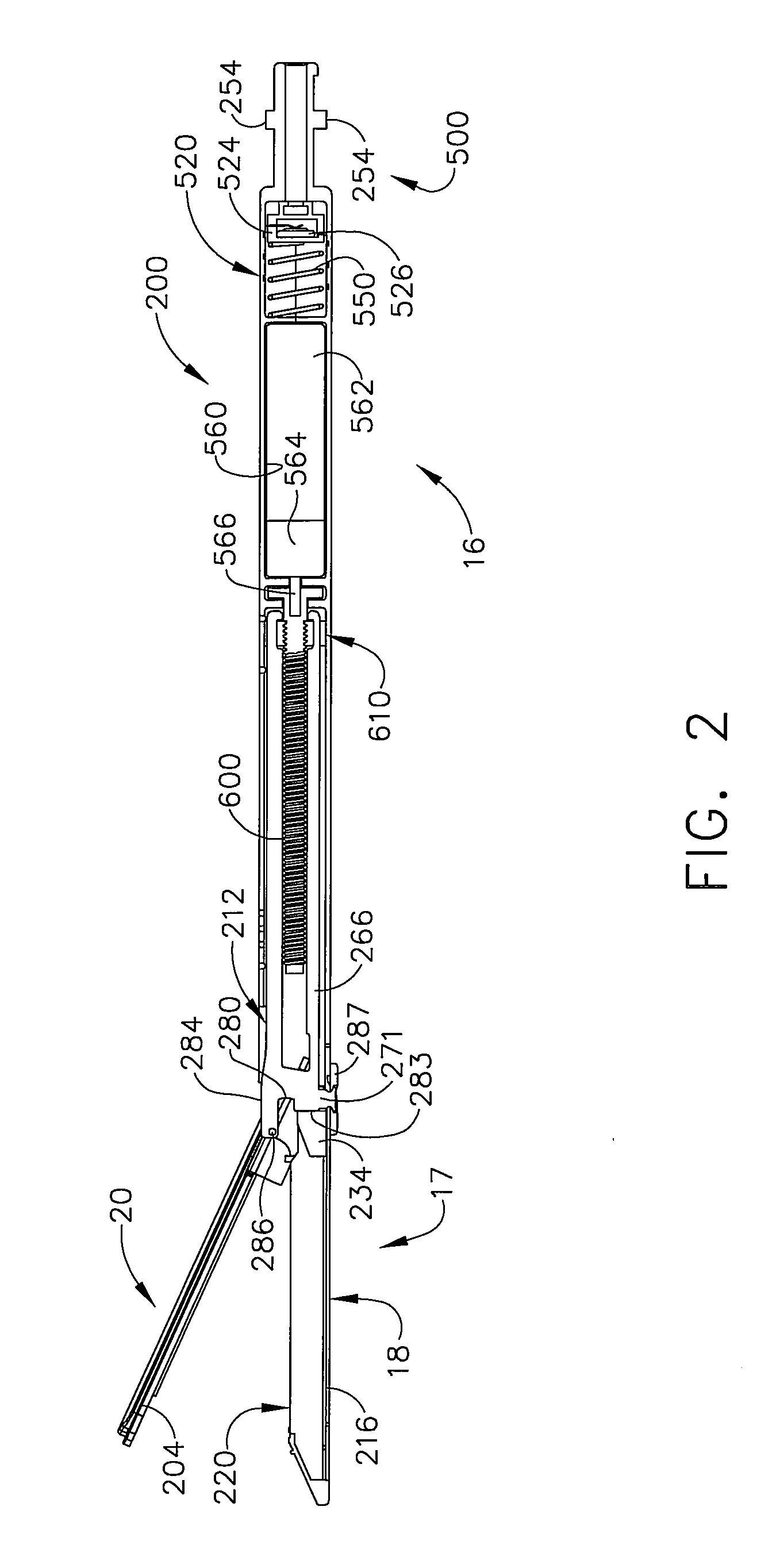
Turning to the Drawings, wherein like numerals denote like components throughout the several views, FIG. 1 depicts a disposable loading unit 16 of the present invention that is coupled to a conventional surgical cutting and stapling apparatus 10. The construction and general operation of a cutting and stapling apparatus 10 is described in U.S. Pat. No. 5,865,361, the disclosure of which has been herein incorporated by reference. Thus, the present Detailed Description will not discuss the various components of the apparatus 10 and their operation herein beyond what is necessary to describe the operation of the disposable loading unit 16 of the present invention.

As the present Detailed Description proceeds, it will be appreciated that the terms “proximal” and “distal” are used herein with reference to a clinician gripping a handle assembly 12 of the surgical stapling apparatus 10 to which the disposable loading unit 16 is attached. Thus, the disposable loading unit 16 is distal with r...


PUM

PropertyMeasurementUnit
Poweraaaaaaaaaa
Electrical resistanceaaaaaaaaaa

Abstract

A self contained motor-powered disposable loading unit for use with a surgical cutting and stapling apparatus. The disposable loading unit may contain a battery that is retained in a disconnected position when the disposable loading unit is not in use and is moved to a connected position when the disposable loading unit is coupled to the surgical cutting and stapling apparatus to permit the motor to be selectively powered thereby. Indicators may be supported on the disposable loading unit to indicate when the axial drive assembly thereof is in a starting position and an ending position. Another indicator may be provided to indicate when the anvil assembly is in a closed position.

Description

FIELD OF THE INVENTIONThe present invention relates in general to endoscopic surgical instruments including, but not limited to, surgical cutting and stapling apparatuses that have disposable loading units that are capable of applying lines of staples to tissue while cutting the tissue between those staple lines and, more particularly, to improvements relating to such disposable loading units.BACKGROUNDEndoscopic surgical instruments are often preferred over traditional open surgical devices since a smaller incision tends to reduce the post-operative recovery time and complications. Consequently, significant development has gone into a range of endoscopic surgical instruments that are suitable for precise placement of a distal end effector at a desired surgical site through a cannula of a trocar. These distal end effectors engage the tissue in a number of ways to achieve a diagnostic or therapeutic effect (e.g., endocutter, grasper, cutter, staplers, clip applier, access device, dru...

Claims


Application Information

Patent Timeline
IPC IPC(8): A61B17/068
CPCA61B17/07207A61B2017/00734A61B2017/00398A61B2017/00017
Inventor MOORE, KYLE P.SHELTON, IV, FREDERICK E.WEISENBURGH, II, WILLIAM B.MORGAN, JEROME R.RANSICK, MARK H.TIMPERMAN, EUGENE L.
Owner CILAG GMBH INTERNATIONAL
Learn More