
Apparatus for making tenons and forming shoulders on wood ends

a technology of forming apparatus and tenon, which is applied in the direction of tongue/groove making apparatus, wood-turning machine, manufacturing tools, etc., can solve the problems of limited or no functionality, inadequate routing of wood guides, and present tools that do not serve the purpos

Inactive Publication Date: 2011-06-09
SMITH LESLIE GENE
View PDF3 Cites 1 Cited by
  • Summary
  • Abstract
  • Description
  • Claims
  • Application Information

AI Technical Summary

Benefits of technology

[0011]A further object of the invention is To provide a apparatus that will form differently shaped shoulders using different router heads and change the profile cut of the router head.

Problems solved by technology

However, routers fitted with wood guides may be inadequate for the current needs of the industry as they offer limited or no functionality since they require the log end to be cut square prior to placing a tenon on a log.
The present tools offer no functionally for the purposes of making tapered tenon.
To enhance each feature of a wood guide to the specifications of different router heads may be counter-productive to cost.
Furthermore, the tenon makers present in the market have no specifications on how to threads on a tenon with different thread pitches.
The user may also not be able to choose the option of adding threads or grooves as per specific measurements.
As such there are no tools on the market for this clear specification and hence the user may be unable to craft such a joint for his needs.
Furthermore, the user may have a need of a spiral dowel pins which a normal router apparatus present may be unable to craft.
The user may be at loss to craft tenons of a specific diameter.
Furthermore the user may have a need to craft tenons with different types of shoulders and this need remains unfulfilled with the limitation of router apparatuses present in the market.

Method used


Image

  • Apparatus for making tenons and forming shoulders on wood ends
  • Apparatus for making tenons and forming shoulders on wood ends
  • Apparatus for making tenons and forming shoulders on wood ends

Examples


Embodiment Construction

[0034]Detailed descriptions of the preferred embodiment are provided herein. It is to be understood, however, that the present invention may be embodied in various forms. Therefore, specific details disclosed herein are not to be interpreted as limiting, but rather as a basis for the claims and as a representative basis for teaching one skilled in the art to employ the present invention in virtually any appropriately detailed system, structure or manner.

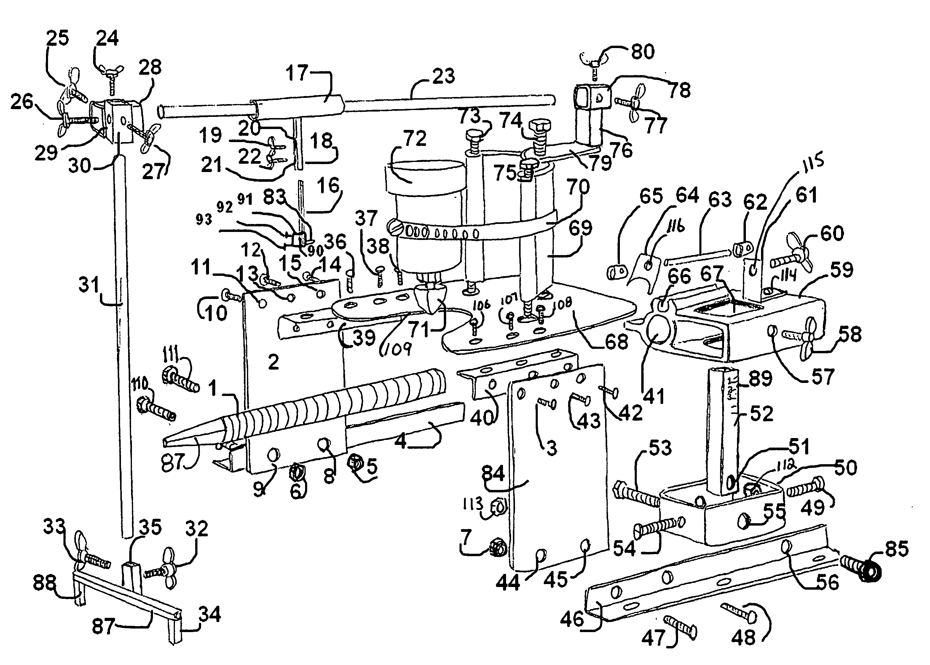
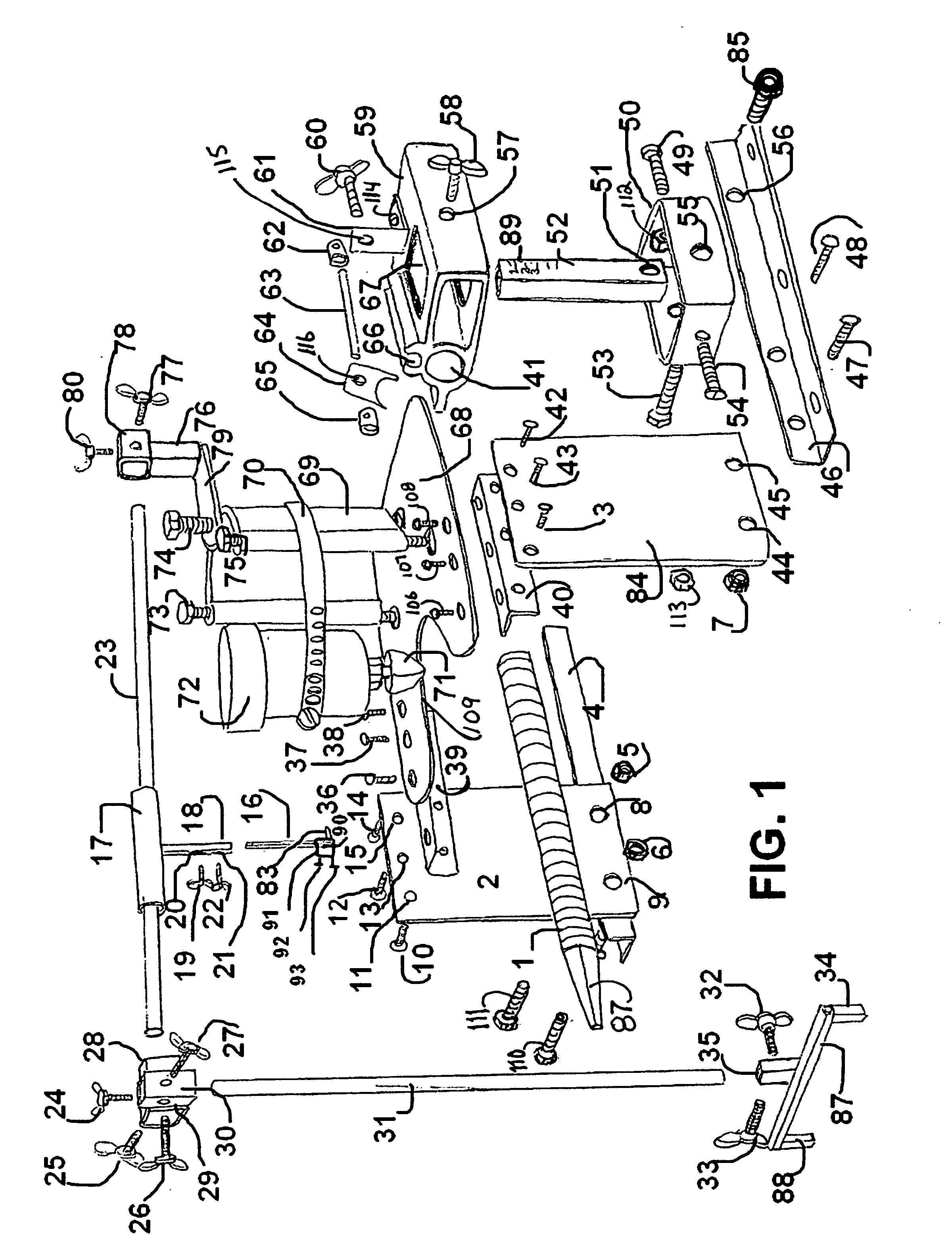
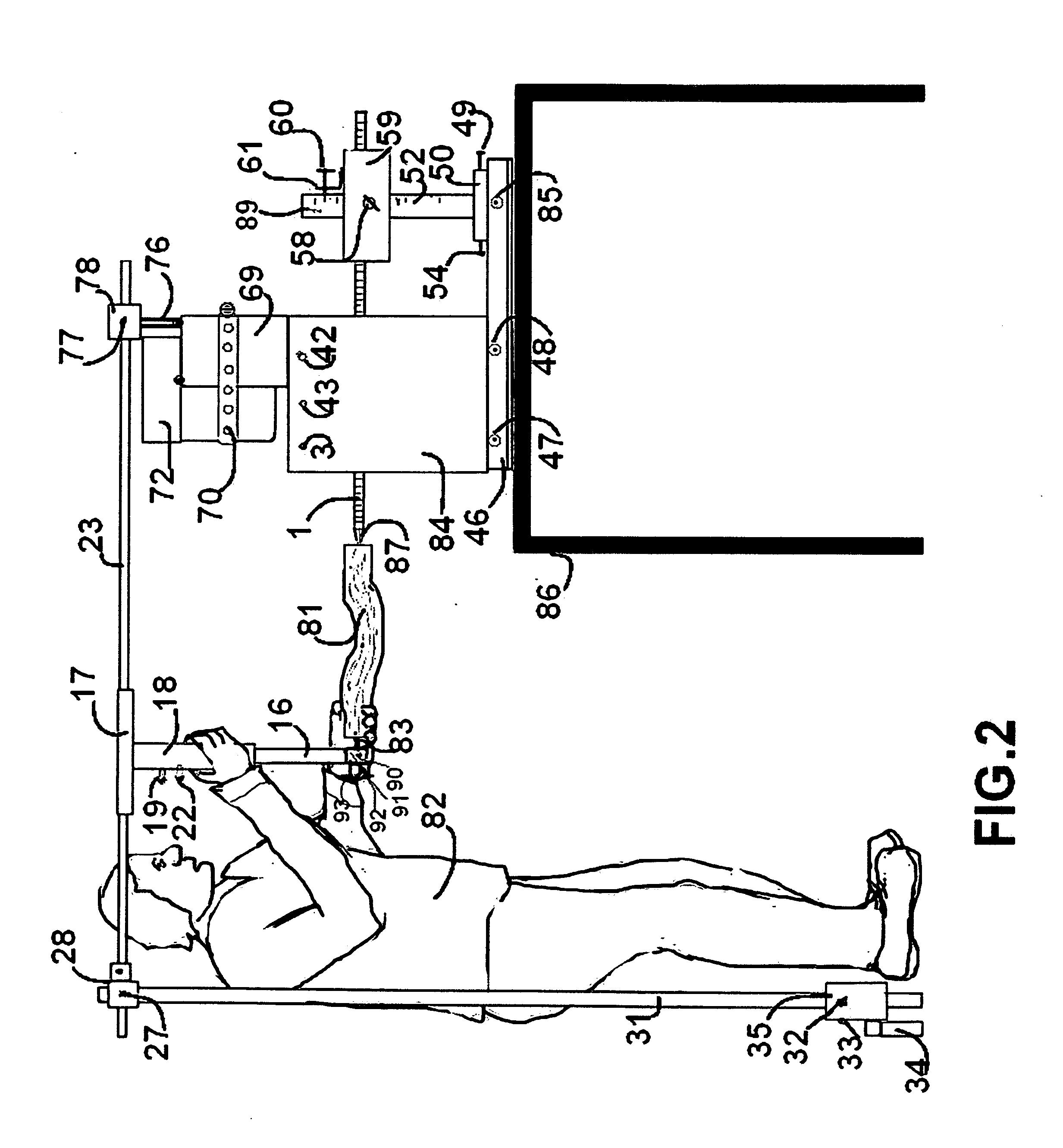
[0035]What is disclosed is a method, apparatus, and adjustable tenon making and shoulder forming apparatus for a router or spindle motor. Turning now descriptively to the drawings in which similar reference characters denote similar elements throughout the several views, the attached figures illustrate a tenon making and shoulder forming apparatus which comprising of a attachable stand top 68 that has a slot 109 in the front so the router motor 72 with a router head 71 can be removed without having to remove the router head 71, diffe...


PUM


Abstract

Apparatus for making tenons and forming shoulders on wood ends with a stand having two opposing sides and a attachable stand top, a two piece router bracket that accepts different diameter router motors, a threaded rod bracket with at least 3 apertures for receiving a threaded rod, a threaded rod with a square tapered end, a tube connector that receives and secures smaller round diameter tubing and bolts to the top of the router bracket, a round steel slide pole, a wooden work piece holder with a round tube with a square tube attached at a 90 degree angle a a square tube with a fixed stud at one end. A preferred embodiment includes the curved thread engaging clip moves slidably on a steel rod. A preferred embodiment includes locking collars used as adjustable stops positioning the curved engaging clip in a engaging and disengaging location on the threaded rod.

Description

CROSS REFERENCE TO RELATED APPLICATIONS[0001]This application is based on provisional application Ser. No. 61 / 267,880, filed on Dec. 9, 2009.STATEMENT REGARDING FEDERALLY SPONSORED RESEARCH OR DEVELOPMENT[0002]Not ApplicableDESCRIPTION OF ATTACHED APPENDIX[0003]Not ApplicableBACKGROUND OF THE INVENTION[0004]This invention relates generally to the field of mechanical technology in the field of woodworking and more specifically to a method, apparatus and system for a adjustable tenon and shoulder forming apparatus for a spindle or router motor. Mortise and tenon joints are traditional woodworking methods to provide support to structures of wood that contain right angles. Tenons are usually projections at the end of a log which may be made of timber or other wood. Traditionally, the ends of the logs have to be narrowed down to provide for a mortise and tenon joints in woodworking. Some components of the draw-joint process have been mechanized. Mortice- and tenon joints, for example, we...

Claims


Application Information

Patent Timeline
Patent Type & Authority Applications(United States)
IPC IPC(8): B27F1/08
CPCB23Q1/522B27C7/005B27M3/32B27F1/10B27C7/04
Inventor SMITH, LESLIE GENE
Owner SMITH LESLIE GENE
Learn More