
Systems and methods for obtaining dental impressions

a technology of dental impressions and systems, applied in the field of controlled flow can solve the problems of reduced increased chance of unwanted “drag” and other problems, and achieve the effect of facilitating the taking of dental impressions and increasing the hydrodynamic pressure of dental impression materials

Inactive Publication Date: 2011-06-02
RABINOWITZ GARY
View PDF16 Cites 5 Cited by
  • Summary
  • Abstract
  • Description
  • Claims
  • Application Information

AI Technical Summary

Benefits of technology

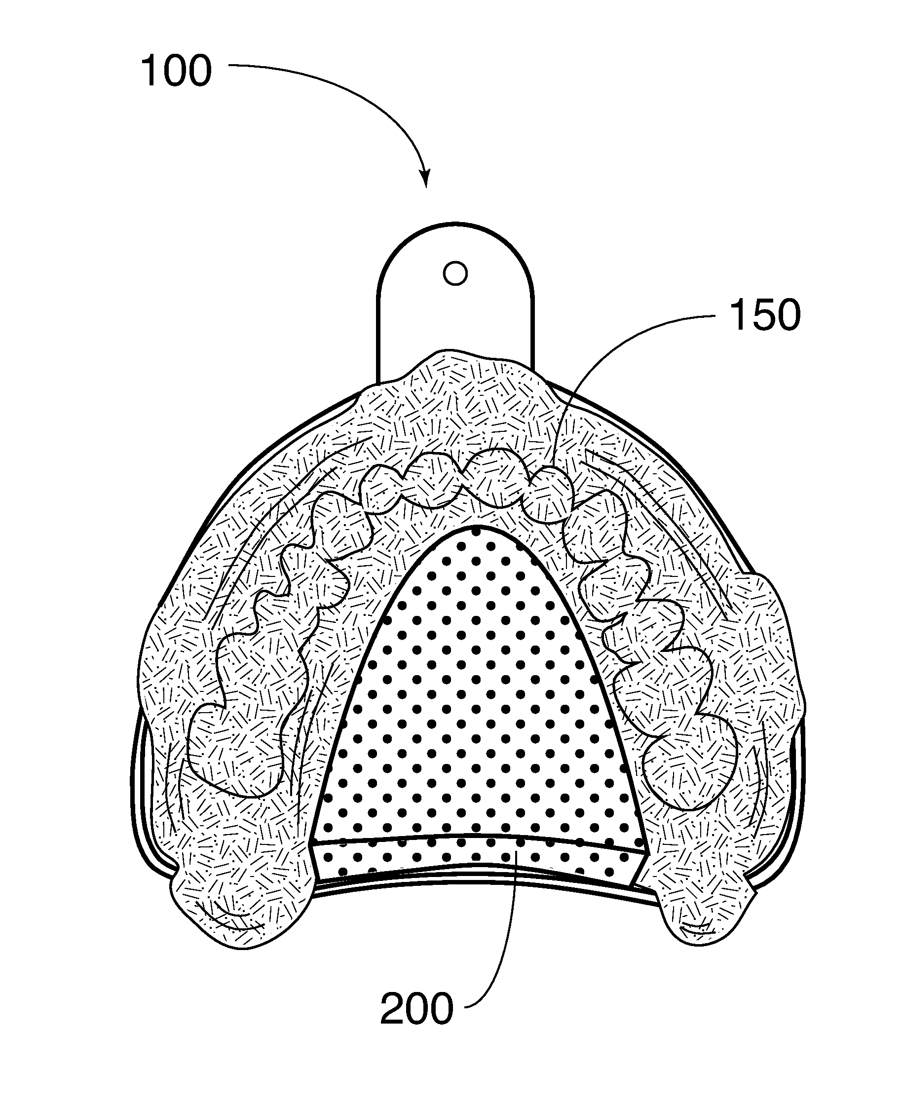
[0011]The top surface forms a seal with the patient's hard palate. This seal discourages dental impression material from flowing into the patient's palatal vault. The seal may also discourage the dental impression material from flowing into the back of the patient's mouth. Consequently, the hydrodynamic pressure of the dental impression material may be advantageously increased and the patient's comfort may be increased. Furthermore, the seal may promote a hydrodynamic flow of the dental impression material against the patient's teeth and corresponding gingival sulcus. When the compressible body compresses, the outer border may expand. This expansion may lead to further promotion of the hydrodynamic pressure and flow of the dental impression material.
[0016]Certain embodiments of the present invention provide a method for facilitating the taking of a dental impression. A compressible body is adhered to a palate area of a maxillary dental impression tray. The compressible body is then compressed against the patient's hard palate and a seal is formed. Consequently, dental impression material is discouraged from flowing into the patient's palatal vault. The dental impression material is also discouraged from flowing into the back of the patient's mouth. The compressible body has an outer border that may expand in response to the compression of the compressible body. As a consequence, the hydrodynamic pressure of the dental impression material may be increased.

Problems solved by technology

In addition to creating discomfort in a patient, such unwanted flow may cause reduced hydrodynamic pressure of the dental impression material.
Such reduction may lead to a degraded casting.
For example, there may be an increased chance of “drag”—an unwanted creeping movement of dental impression material.
One problem that may result from inadequate regulation is “over-seating”, in which a patient's teeth sink too close to the bottom of the dental impression tray.

Method used


Image

  • Systems and methods for obtaining dental impressions
  • Systems and methods for obtaining dental impressions
  • Systems and methods for obtaining dental impressions

Examples


Embodiment Construction

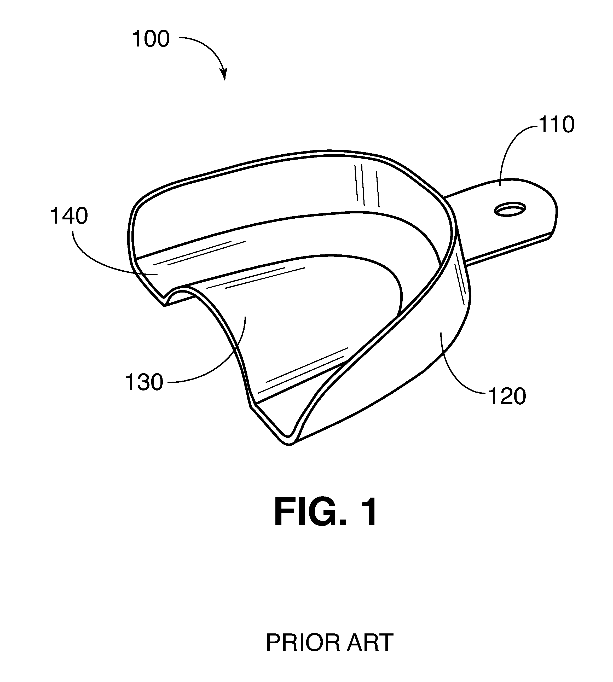
[0027]FIG. 1 shows a maxillary dental impression tray 100. The tray may include a handle 110, an outer wall 120, a palate area 130, and a well 140.

[0028]The tray 100 is configured to hold dental impression material (not shown) in the well 140. The tray 100 may be used by inserting it into a patient's mouth and pressing upward towards the patient's maxillary teeth or jaw. The handle 110 may be used to facilitate insertion and removal of the tray 100 into the patient's mouth. The well 140 may be generally formed between the outer wall 120 and the palate area 130. Maxillary dental impression trays are known, and as used herein are confined to the specific examples described herein.

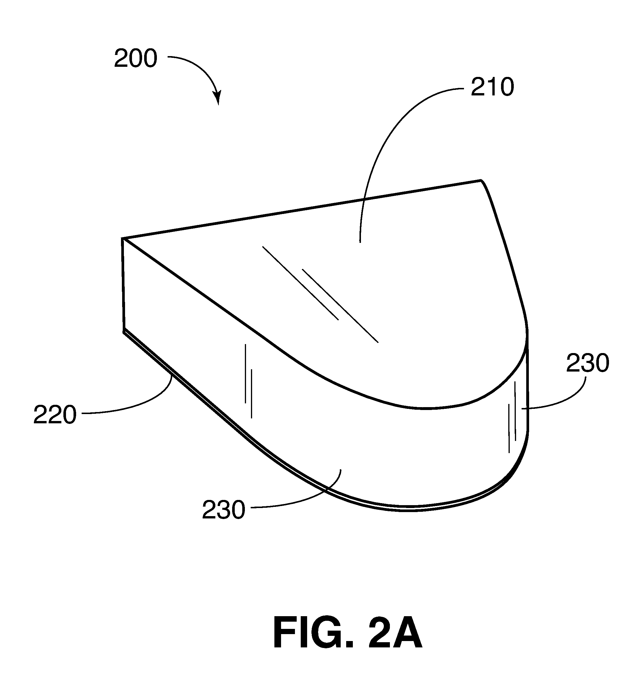
[0029]FIG. 2A shows a compressible body 200, according to an embodiment of the present invention. The compressible body 200 may include a top surface 210, a bottom surface 220, and an outer border 230.

[0030]The compressible body 200 may include a compressible material, such as foam. For example, the compressi...


PUM


Abstract

Certain embodiments of the present invention provide an apparatus to facilitate obtaining a dental impression including a compressible body. The compressible body has a top surface, a bottom surface, and an outer border. The bottom surface is configured to abut a maxillary dental impression tray. The top surface of the compressible body is configured to substantially contact and conform to a surface of a patient's hard palate. As the top surface contacts and conforms to the hard palate, it causes the compressible body to compress. The top surface forms a seal with the patient's hard palate. This seal discourages dental impression material from flowing into the patient's palatal vault. The seal may also discourage the dental impression material from flowing into the back of the patient's mouth. Consequently, the hydrodynamic pressure of the dental impression material may be advantageously increased and the patient's comfort may be reduced. Furthermore, the seal may promote a hydrodynamic flow of the dental impression material against the patient's teeth and into the corresponding gingival sulcus. When the compressible body compresses, the outer border may expand. This expansion may lead to further promotion of the hydrodynamic presser and flow of the dental impression material.

Description

RELATED APPLICATIONS[0001]This application claims priority to U.S. Provisional Patent Application No. 61 / 265,141, filed on Nov. 30, 2009, which is herein incorporated by reference.FEDERALLY SPONSORED RESEARCH OR DEVELOPMENT[0002][Not Applicable]MICROFICHE / COPYRIGHT REFERENCE[0003][Not Applicable]BACKGROUND OF THE INVENTION[0004]The present invention relates generally to controlled flow of dental impression materials. More specifically, it relates to a flexible and / or compressible addition or component in dental impression trays.[0005]Certain dental procedures require castings of dental surfaces. The castings may be formed from dental impression material. In order to obtain or take the casting, the dental impression material may be placed into a tray, such as a maxillary or upper dental tray. The dental impression material may initially be a somewhat viscous liquid or flowing material. A dental impression tray may be loaded with the impression material and inserted in a patient's mou...

Claims


Application Information

Patent Timeline
Patent Type & Authority Applications(United States)
IPC IPC(8): A61C9/00
CPCA61C9/0006A61C9/00
Inventor RABINOWITZ, GARY
Owner RABINOWITZ GARY
Learn More