
Fiber optics dental post

a fiber optics and dental post technology, applied in the field of dental posts, can solve the problems that the denture body cannot be easily shed off or damaged, and achieve the effects of improving the structural bonding strength of the denture body and the adhesion strength of the dental post, and enhancing the light-guide effect of the dental pos

Active Publication Date: 2011-06-02
TAIWAN FIBER OPTICS
View PDF13 Cites 11 Cited by
  • Summary
  • Abstract
  • Description
  • Claims
  • Application Information

AI Technical Summary

Benefits of technology

[0008]The present invention can effectively enhance the light-guide effect of the dental post through the structural design of the fiber optics dental post. Thus, the received light can be propagated to the outer peripheral face and the bottom of the resin body through the light-guide irradiation end of the fiber optics dental post for irradiation, so as to effectively make the adhesive to be cured and adhesive through full irradiation by the light, and to effectively improve the structural bonding strength of the denture body and the adhesion strength of the dental post. As a result, the denture body will not easily shed off or be damaged. With the structural design of the fiber optics dental post, the present invention can effectively enhance the light-guide effect of the dental post and make the adhesive to be cured and adhesive through full irradiation by the light, and through the structural design of the resin body with opacity of X-ray irradiation, the structural strength of the fiber optics dental post is enhanced, so as to be useful and convenient in use.

Problems solved by technology

As a result, the denture body will not easily shed off or be damaged.

Method used


Image

  • Fiber optics dental post
  • Fiber optics dental post
  • Fiber optics dental post

Examples


Embodiment Construction

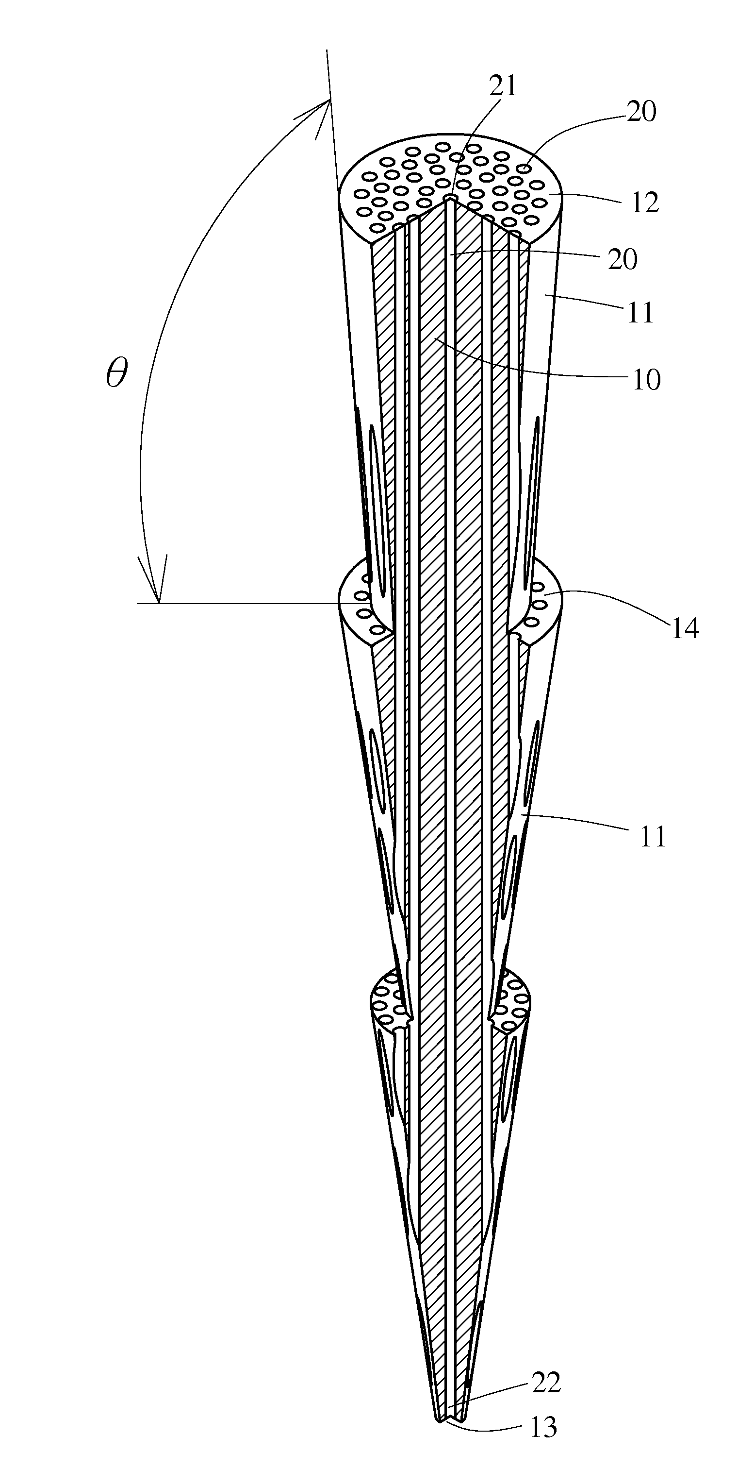
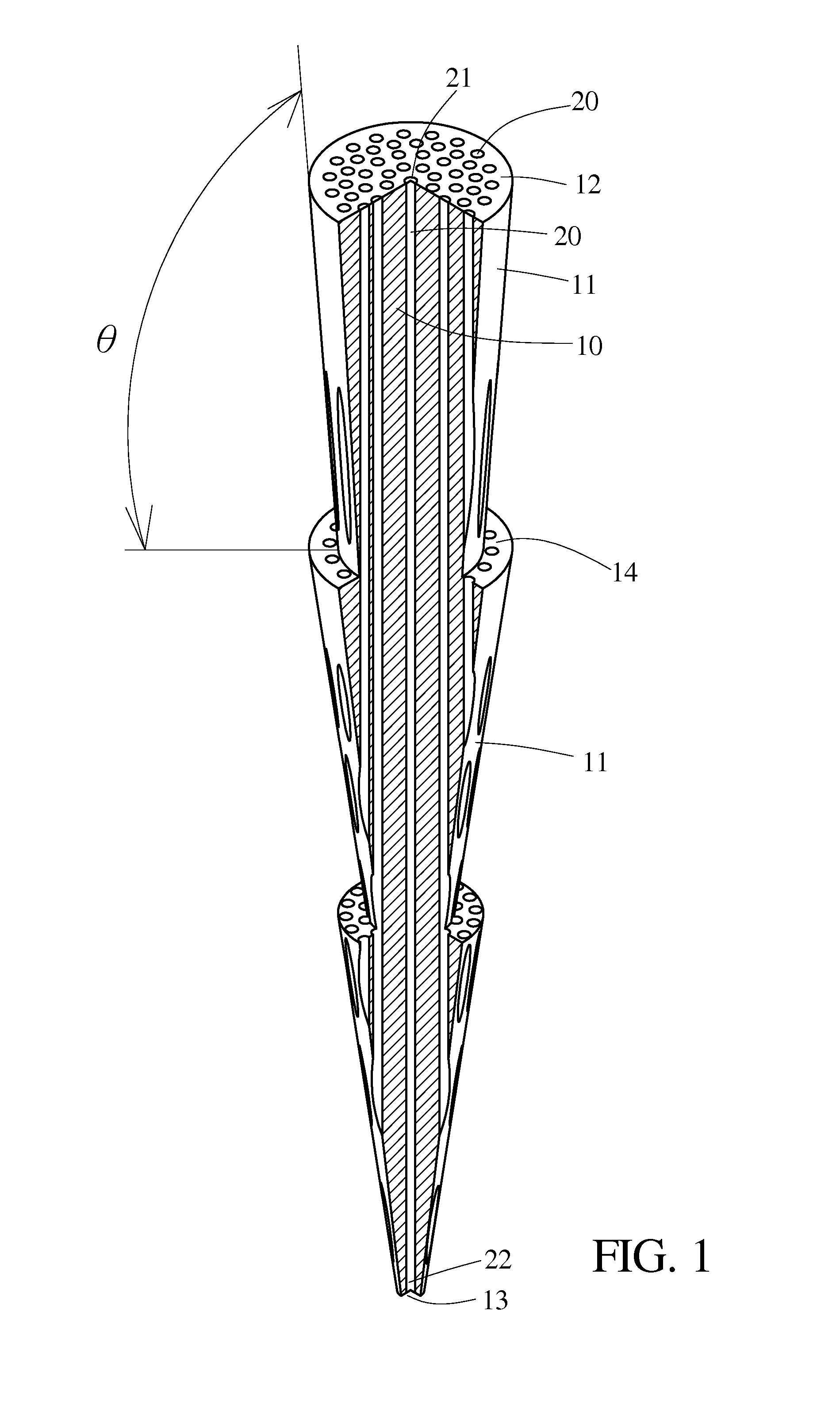
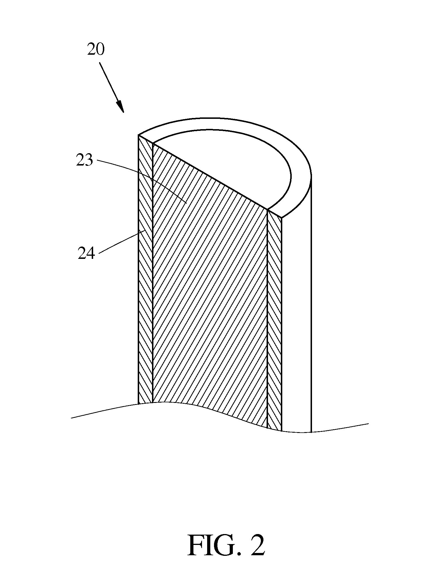
[0021]Referring to FIG. 1 to FIG. 11, the present invention provides a fiber optics dental post including: a resin body 10 and plural fiber optics center shafts 20. In which, the resin body 10 includes an outer peripheral face 11, a receiving irradiation portion 12, and a bottom 13; each of the fiber optics center shafts 20 pierces through and is fixed in the resin body 10 for shaping, and has a receiving irradiation end 21 and a light-guide irradiation end 22; each receiving irradiation end 21 placed on the receiving irradiation portion 12 of the resin body 10 is used to receive the light irradiating on the receiving irradiation portion 12, and each light-guide irradiation end 22 is respectively placed on the outer peripheral face 11 and at the bottom 13 of the resin body 10, thus the light received by each receiving irradiation end 21 is propagated to the outer peripheral face 11 and the bottom 13 of the resin body 10 through the light-guide irradiation end 22 for irradiation. In ...


PUM


Abstract

A fiber optics dental post includes a resin body and plural fiber optics center shafts; wherein the resin body includes an outer peripheral face, a receiving irradiation portion, and a bottom; each of the fiber optics center shafts pierces through and is fixed in the resin body, and has a receiving irradiation end and a light-guide irradiation end; each receiving irradiation end placed on the receiving irradiation portion of the resin body is used to receive the light irradiating on the receiving irradiation portion, and each light-guide irradiation end is respectively placed on the outer peripheral face and at the bottom of the resin body, thus the light received by each receiving irradiation end is propagated to the outer peripheral face and the bottom of the resin body through the light-guide irradiation end for irradiation, so as to effectively enhance the adhesion strength of the dental post.

Description

BACKGROUND OF THE INVENTION[0001]1. Field of Invention[0002]The present invention relates to a technical field of dental posts, more specifically to a fiber optics dental post with light-guide effect and opacity of X-ray.[0003]2. Description of the Related Art[0004]For a patient with serious caries or partial anodontia, dentists generally advise the patient to make a dental crown or bridge to recover the health of oral cavity and functions of a tooth; a dental crown or bridge adhered to the tooth of a patient is commonly referred to as fixed dental prosthesis; if a tooth is destroyed because of serious curiosity or injury, after root canal treatment, only fillings may not properly protect the tooth and recover functions thereof, and if the tooth accidentally bites a hard object, the tooth may be destroyed and need for extraction, thus the tooth must be covered with a dental crown.[0005]Referring now to FIG. 12, a conventional denture generally includes a denture body 40 and a dental...

Claims


Application Information

Patent Timeline
Patent Type & Authority Applications(United States)
IPC IPC(8): A61C19/00
CPCA61C13/30A61C19/003
Inventor LU, LUKE
Owner TAIWAN FIBER OPTICS
Learn More