System and method for optical bypass routing and switching

Inactive Publication Date: 2011-06-02
TELCORDIA TECHNOLOGIES INC
View PDF8 Cites 13 Cited by
  • Summary
  • Abstract
  • Description
  • Claims
  • Application Information

AI Technical Summary

Benefits of technology

[0009]The method is achieved in two phases. In the first phase, each node independently determines the maximum number of optical bypass circuits, each configured to carry a specified amount of traffic, to as many destinations, not necessarily final destination nodes of the traffic demand, that could possibly originate at that node. Each optical bypass circuit has some specified bandwidth, such as a high percentage of a wavelength's full capacity. The optical bypass circuit transports traffic that originates at the node plus transient traffic that the node receives from other nodes. In other words, all traffic is

Problems solved by technology

The enormous growth of the data traffic on the backbone networks stresses the transmission bandwidth and burdens the processing capability of the electronic routers, switches, and multiplexers used in the backbone network.
However, this increased transmission rate will burden the existing electronic routers and switches used in nodes of the network.
Although the emergence of optical bypass techniques appears to be a promising solution, there are challenges in incorporating these techniques in an IP network.

Method used


Image

  • System and method for optical bypass routing and switching
  • System and method for optical bypass routing and switching
  • System and method for optical bypass routing and switching

Examples


Embodiment Construction

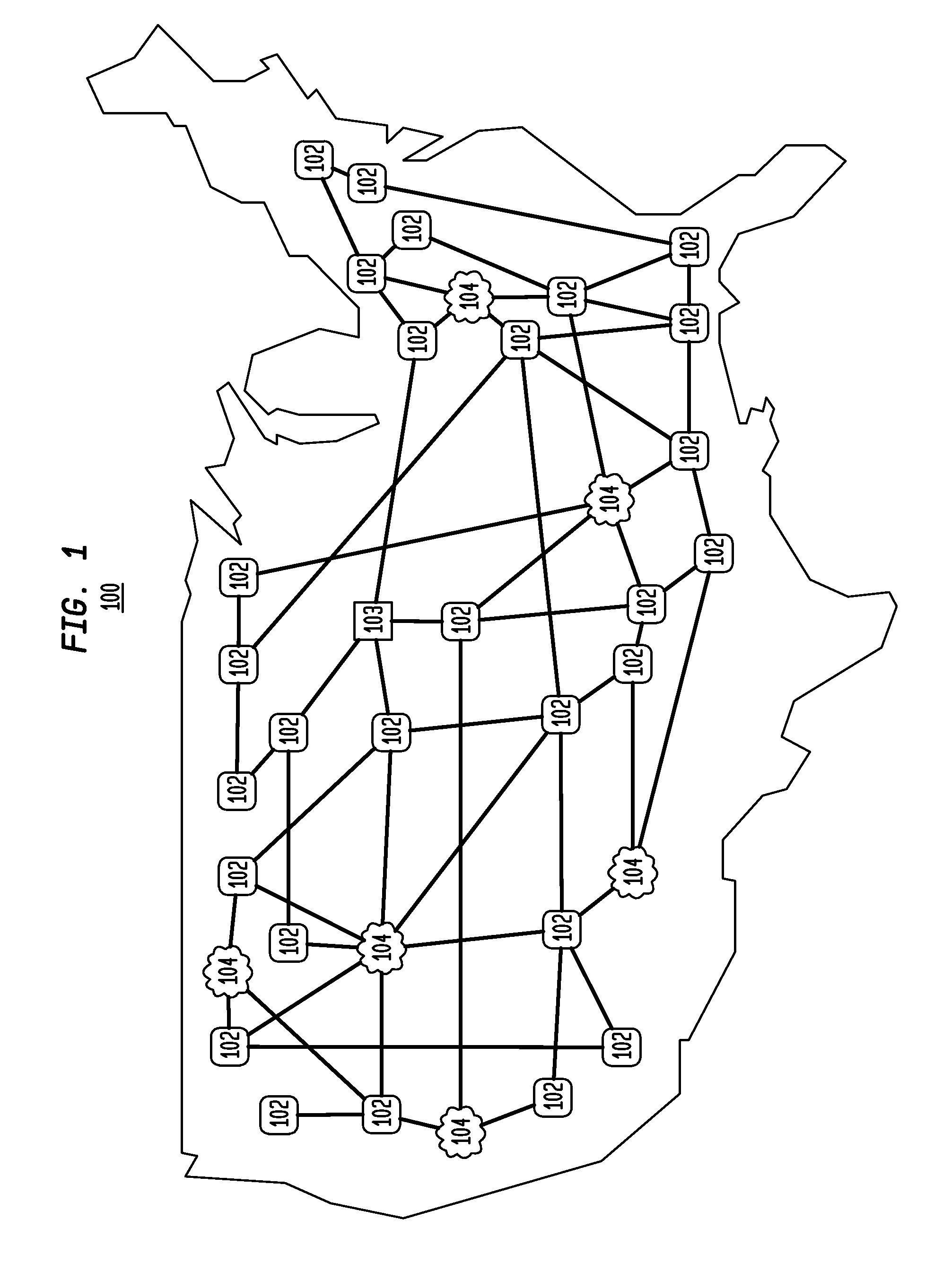
[0020]FIG. 1 illustrates an embodiment of a network configuration utilizing the technology described herein. There is shown an arbitrary mesh network 100 composed of a number of nodes, 102, and networks 104, interconnected to each other to facilitate the transmission of data packets within the network 100. The network 100 can be a core or backhaul network. The network 100 employs an arbitrary mesh topology wherein each node 102 in the network 100 is connected to one or more nodes 102 in the network 100. The connection between nodes 102 in the network 100 is dynamic and can be reconfigured in the event of broken or blocked paths. Nodes 102 in a mesh network do not require a direct connection between all the other nodes 102, rather the connection can be made through multiple hops through intermediate nodes.

[0021]The nodes 102 can be connected to other networks 104 and can facilitate communication between the different networks 104. The nodes are connected via any type of communication...


PUM


Abstract

Optical bypass circuits are selected and created with a desired amount of traffic on each circuit to offload from the IP routers, the maximum possible amount of traffic. In a first phase, each node in a network independently determines the maximum number of optical bypass circuits, configured to their maximum capacity, to as many destinations, that could possibly originate at that node. The determination is made by aggregating traffic from a given traffic matrix. The optical bypass circuit transports traffic that originates at the node plus transient traffic that the node receives from other nodes. In the second phase, the node will eliminate an optical bypass circuit found in the first phase if any of its parent nodes created a necessarily longer optical bypass circuit to the same destination. In addition, if a descendent node has more aggregate traffic to fill more bypass circuits than the parent node, then the extra optical bypass circuits from the descendent node are also created.

Description

CROSS REFERENCE TO RELATED APPLICATIONS[0001]This application claims the benefit of the filing date of U.S. Provisional Application No. 61 / 254,778, filed on Oct. 26, 2009, the disclosures of which are incorporated herein by reference.STATEMENT REGARDING FEDERALLY SPONSORED RESEARCH OR DEVELOPMENT[0002]Funding for research was made with Government support under HR011-09-C-0024 awarded by the Defense Advanced Research Projects Agency (DARPA). The Government has certain rights to this invention.BACKGROUND[0003]1. Field of the Invention[0004]The present invention relates generally to the field of communication networks, and more particularly to the design of optical bypass routing and switching in communication networks.[0005]2. Description of the Related Art[0006]The increasing popularity of the Internet has increased traffic demands on the backbone networks supporting the Internet. The enormous growth of the data traffic on the backbone networks stresses the transmission bandwidth and...

Claims


Application Information

Patent Timeline
IPC IPC(8): H04J14/00
CPCH04J14/0212H04J14/0269H04J14/0267H04J14/0257
Inventor KAROL, MARK
Owner TELCORDIA TECHNOLOGIES INC
Why Eureka
Try Eureka