
Wheel suspension

a technology of suspension and wheel, applied in the direction of shock absorbers, machine supports, transportation and packaging, etc., can solve the problems of occupying a large space and achieve the effect of reducing installation space and simplifying the configuration of spring elements

Active Publication Date: 2011-06-02
FORD GLOBAL TECH LLC
View PDF20 Cites 4 Cited by
  • Summary
  • Abstract
  • Description
  • Claims
  • Application Information

AI Technical Summary

Benefits of technology

[0012]It is therefore the object of the invention to improve a wheel suspension of the type mentioned in the introduction with simple means in such a manner that McPherson wheel suspensions, for example, have advantages regarding installation space, considerable economies being achievable at the same time, in particular as a result of a simpler configuration of the spring element.
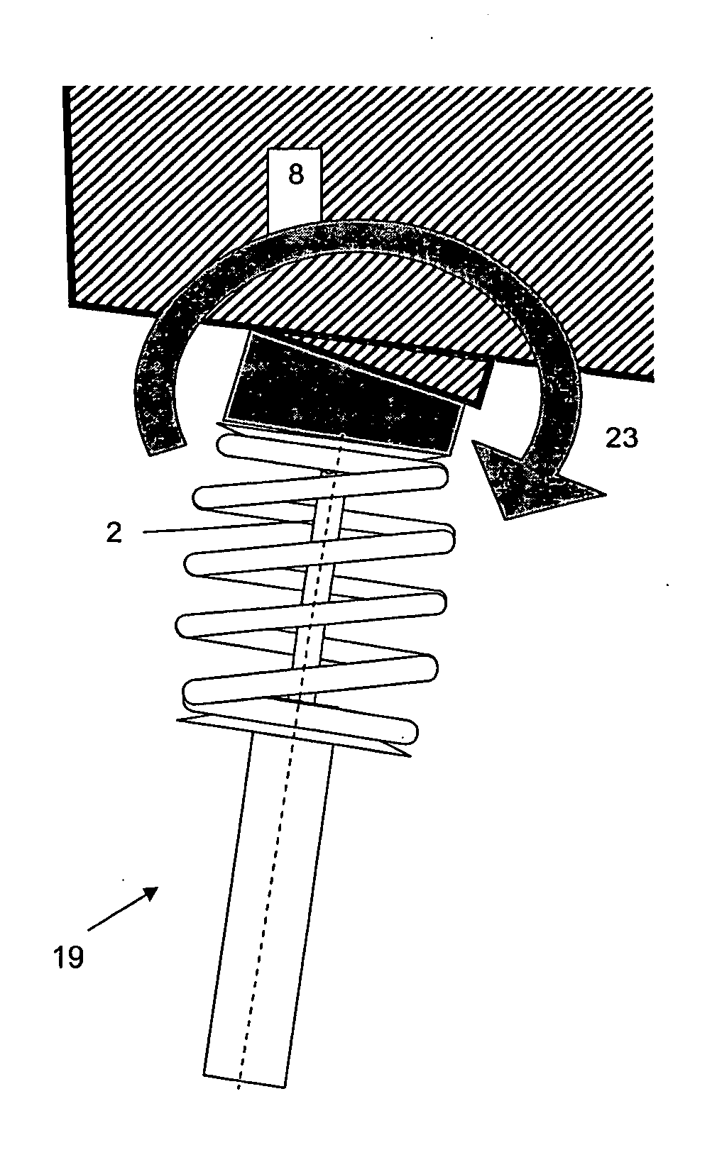
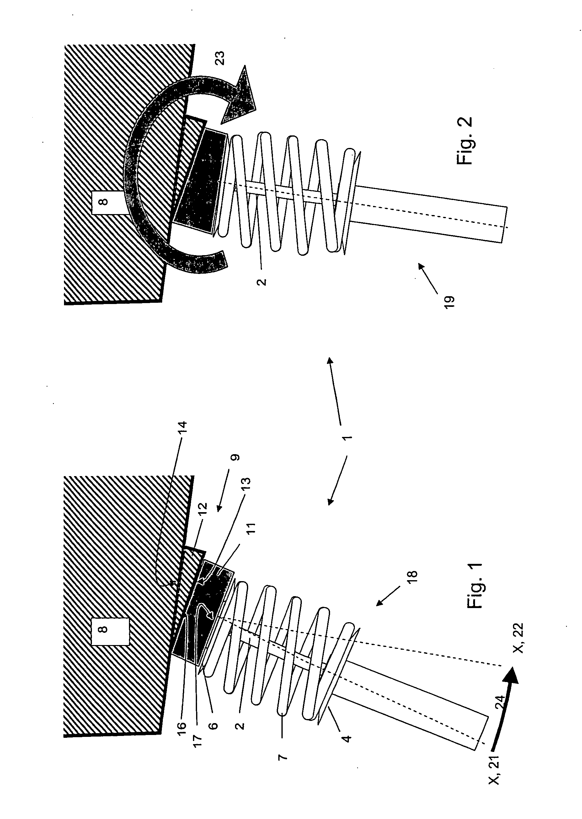
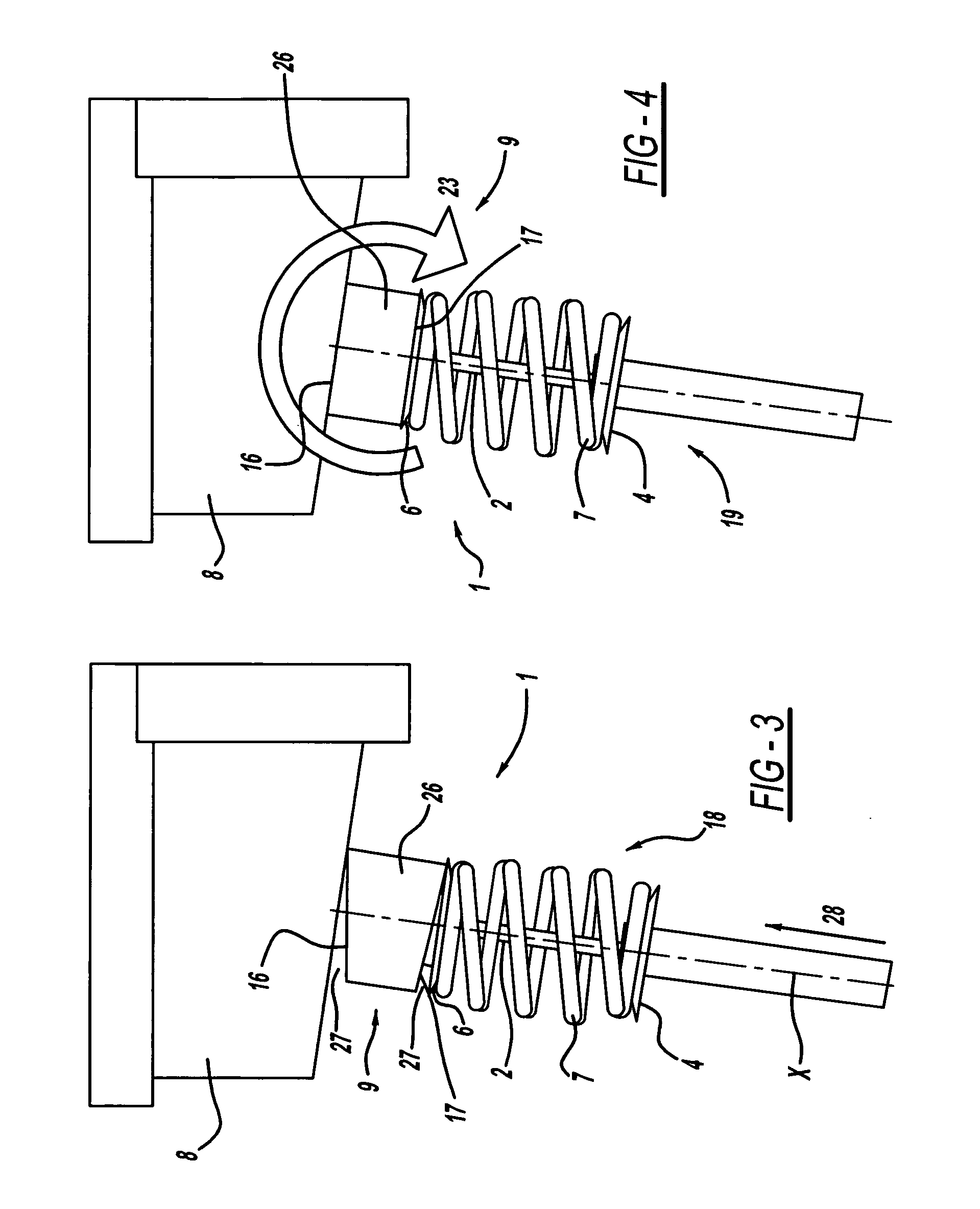
[0014]The invention makes available a wheel suspension, for example a McPherson wheel suspension, which influences a shock absorber prestress and generates an internal moment between the vehicle body and the spring element and / or the shock absorber, on the front or rear axle of the vehicle. In this case the prestress is generated during assembly or during the installation of the damper strut or of the shock absorber. Ideally, the amount of the internal moment compensates the bending moment of the shock absorber for certain types of loading, it being possible for the amount of the internal moment to be adapted to this certain type of loading. In the case of McPherson wheel suspensions, the inventive solution results in advantages with regard to installation space, since the configuration of the spring element or of the helical spring is simpler, without the use of special measures. For example, a specially installed helical spring which in the installed state has a greater prestress on a half of the helical spring oriented, for example, towards the outside of the vehicle than on the half oriented towards the inside of the vehicle can be dispensed with. With the invention, an angled arrangement of the center line of the helical spring with respect to the center line of the shock absorber can be dispensed with. The helical spring can therefore be configured and produced more cost-effectively, since material savings are also possible.

Problems solved by technology

However, this can lead to considerable problems regarding installation space, for example in relation to enlarged wheels or tires.

Method used


Image

  • Wheel suspension
  • Wheel suspension
  • Wheel suspension

Examples


Embodiment Construction

[0027]In the different figures, identical parts are always provided with the same reference numerals, so that as a rule these parts are described only once.

[0028]FIG. 1 shows a section of a wheel suspension with a shock absorber 1 or with a McPherson strut 1. Further elements of the wheel suspension have been omitted from the representation.

[0029]The shock absorber 1 has a piston rod 2. The shock absorber 1 has, in the drawing plane, a lower spring retaining plate 4 and an upper spring retaining plate 6. A spring element 7, in the form of a helical spring 7 in the exemplary embodiment, is arranged between the two spring retaining plates 4, 6. The end of the piston rod 2 is connected to the upper spring retaining plate 6. The head of the shock absorber 1 is connectable to a vehicle body 8.

[0030]An intermediate element system 9 is arranged between the upper spring retaining plate 6 and the vehicle body 8.

[0031]In the exemplary embodiment represented by way of example in FIGS. 1 and 2,...


PUM


Abstract

The invention relates to a wheel suspension having a shock absorber (1) with a piston rod (2) and a spring element (7), the spring element (7) being mounted between a lower spring retaining plate (4) and an upper spring retaining plate (6) and the head of the shock absorber (1) being fastened to a vehicle body (8). An intermediate element system (9, 11, 12; 9, 26) is arranged and embodied between the upper spring retaining plate (6) and the vehicle body (8) in such a manner that a compensating moment (23) is generated during final installation of the shock absorber (1) on the vehicle body (8).

Description

BACKGROUND OF THE INVENTION[0001]The invention relates to a wheel suspension having a shock absorber with a piston rod and a spring element, it being possible for the spring element to be mounted, for example, between a lower and an upper spring retaining plate and the head of the shock absorber being fastened to a vehicle body.[0002]DE 1 505 616 discloses a device for rectilinear guidance of independently suspended wheels, consisting of a hydraulic shock absorber and a helical spring arranged coaxially therewith. The shock absorber is connected to the vehicle body in its upper region and is fastened rigidly to a wheel carrier in its lower region. The helical spring is arranged and configured in such a manner that, in the installed state, the half of the helical spring oriented towards the outside of the vehicle has a greater prestress than the half oriented towards the inside of the vehicle.[0003]In DE 1 630 249 elastic mounts for an engine suspension are described.[0004]An indepen...

Claims


Application Information

Patent Timeline
Patent Type & Authority Applications(United States)
IPC IPC(8): B60G11/54B60G11/14
CPCB60G11/52B60G15/068B60G2204/41B60G2204/128B60G2204/124
Inventor SOUSCHEK, RAINERDAVID, WOLFGANGFRANTZEN, MICHAEL JOHANNESHALFMANN, EDMUNDWOLF-MONHEIM, FRIEDRICH PETER
Owner FORD GLOBAL TECH LLC
Learn More