Fan cowl support cradle mounted on the attachment pylon and on the air inlet of the nacelle

a technology of support cradle and nacelle, which is applied in the direction of aircraft power plant components, machines/engines, transportation and packaging, etc., can solve the problems of affecting the overall performance of the aircraft, and affecting the global geometry of the unit, so as to reduce the space required and reduce the effect of aerodynamics

Active Publication Date: 2011-06-02
AIRBUS OPERATIONS INC AS A
View PDF9 Cites 20 Cited by
  • Summary
  • Abstract
  • Description
  • Claims
  • Application Information

AI Technical Summary

Benefits of technology

[0023]Moreover, even in the case of a loss of a fan blade, the front joint between the cradle and the air inlet implies that the risks of scooping between the front aerodynamic structure and the air inlet of the nacelle are strongly reduced, even reduced to nothing.
[0024]Finally, still due to the presence of the front joint between the cradle

Problems solved by technology

However, when the engine unit is subjected to substantial stresses such as those encountered during the take-off and landing phases, or in flight during strong turbulence, the fixing of the cradle of the front aerodynamic structure to the rigid structure induces a substantial modification of the global geometry of the unit, and more specifically of that of the nacelle.
The phenomenon observed obviously caused the drag, which harms the overall performance of the aircraft.
Moreover, this solution consisting in connecting the cradle on the rigid structure of the attachment pylon causes its overhanging towards the front, which induces substantial mechanical stresses due to the associated mass.
In addition, when the cradle is mounted on the fan case of the engine, this normally causes difficulties in demonstrating the resistance of the front aerodynamic structure to the fan blade loss phenomenon, ph

Method used


Image

  • Fan cowl support cradle mounted on the attachment pylon and on the air inlet of the nacelle
  • Fan cowl support cradle mounted on the attachment pylon and on the air inlet of the nacelle
  • Fan cowl support cradle mounted on the attachment pylon and on the air inlet of the nacelle

Examples


Embodiment Construction

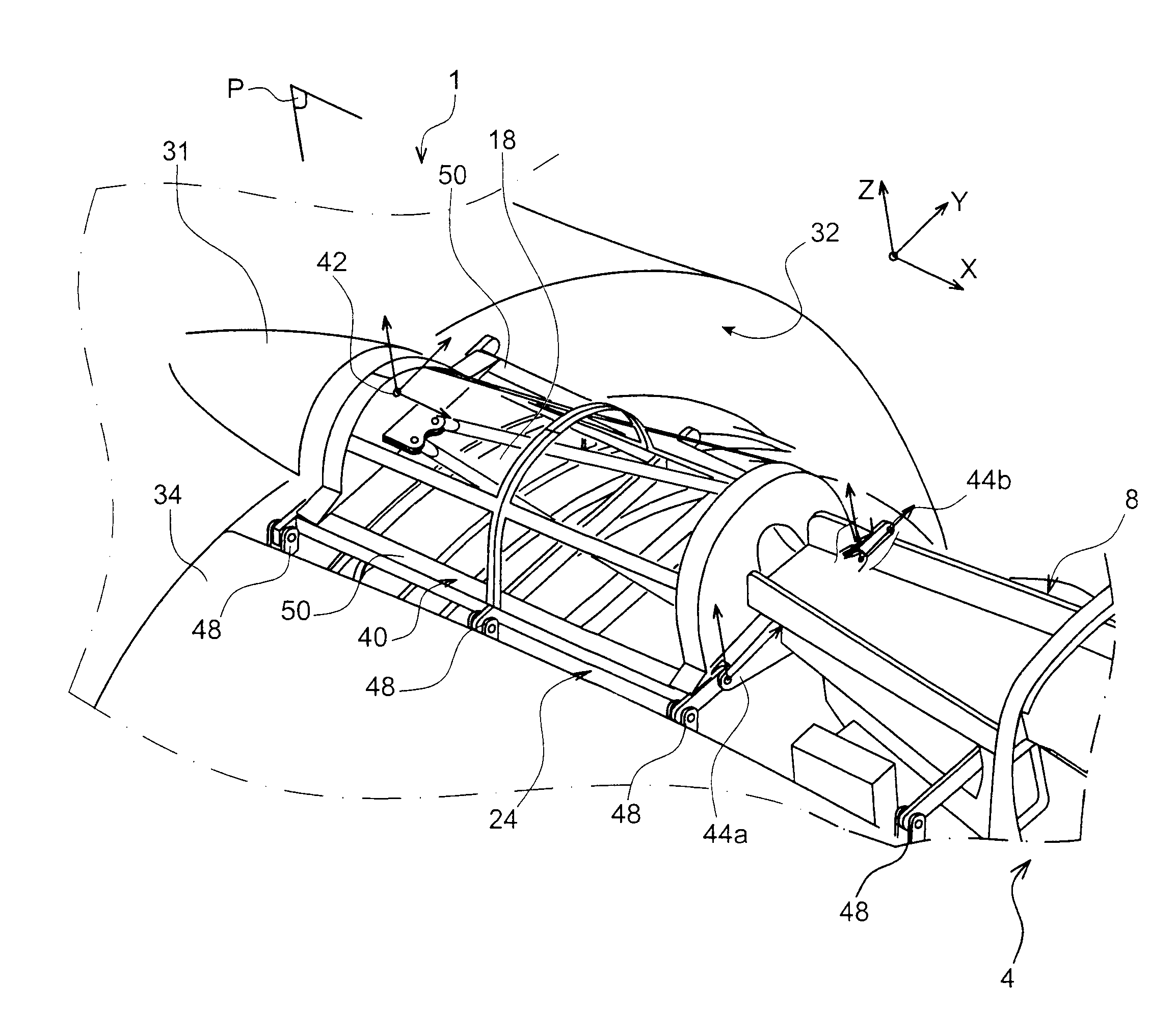
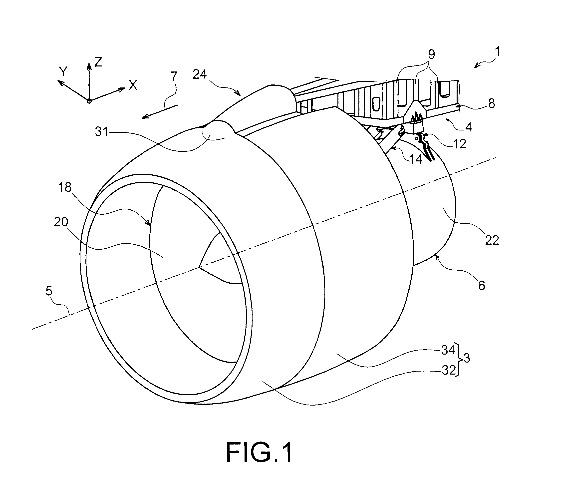
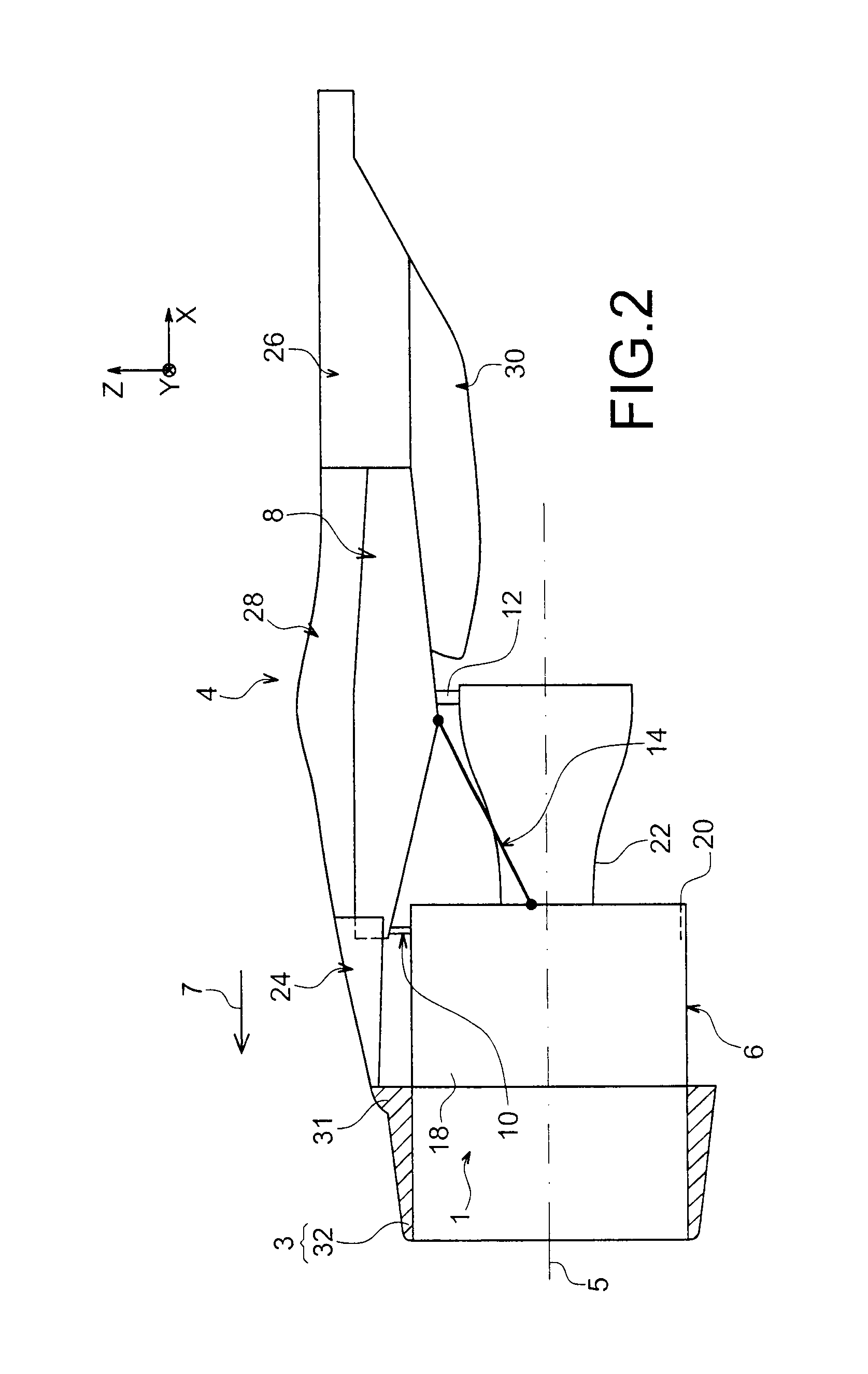
[0048]In reference first of all to FIGS. 1 and 2, an engine unit 1 for aircraft is shown intended to be fixed under a wing of this aircraft (not shown), this unit 1 comprising a device for hooking 4, an engine 6 such as a jet engine fastened under this device 4, and a nacelle 3 of which only the front portion has been shown in FIG. 1.

[0049]In all the description which shall follow, by convention, X shall refer to the longitudinal direction of the device 4 which is also similar to the longitudinal direction of the jet engine 6, this direction X being parallel to a longitudinal axis 5 of this jet engine 6. On the other hand, Y refers to the direction directed transversally in relation to device 4 and also similar to the transversal direction of the jet engine 6, and Z the vertical direction or of the height, these three directions X, Y and Z being orthogdnal to each other.

[0050]On the other hand, the terms “front” and “rear” are to be considered in relation to a forward direction of t...


PUM


Abstract

An engine unit for an aircraft including an engine, a device for hooking the engine, and a nacelle surrounding the engine and provided with fan cowls, the device for hooking including a rigid structure and a front aerodynamic structure whereon the fan cowls are articulated, the front aerodynamic structure including a cradle with a rear mechanism of hooking mounted on the rigid structure. The cradle also includes a front mechanism of hooking mounted on an air inlet of the nacelle.

Description

TECHNICAL FIELD [0001]This invention in general relates to an engine unit for aircraft comprising an engine, a device for hooking the engine as well as a nacelle surrounding the engine and provided with fan cowls as well as an air inlet, the aforementioned device for hooking comprising a rigid structure as well as a front aerodynamic structure whereon the fan cowls are articulated.[0002]This type of device for hooking, also called an attachment pylon or “EMS” (“Engine Mounting Structure”), globally makes it possible to suspend an engine such as a engine below the wing of the aircraft, or to mount this engine above this same wing, or to assemble this engine on a rear portion of the fuselage of the aircraft.PRIOR ART [0003]Such a device for hooking is indeed provided to comprise the connection interface between an engine and a wing of the aircraft. It makes it possible to transmit to the structure of this aircraft the loads generated by its associated engine, and also allows for the r...

Claims


Application Information

Patent Timeline
IPC IPC(8): B64D27/00B64D27/26B64D29/00B64D33/02
CPCB64D27/18B64D2027/264B64D27/26
Inventor DUSSOL, LOICRIDRAY, FREDERIC
Owner AIRBUS OPERATIONS INC AS A
Why Eureka
Try Eureka