Guided mode resonator based raman enhancement apparatus

a raman enhancement and guided mode technology, applied in the field of surface-enhanced raman enhancement systems, can solve the problem of less effective hot spot-based systems

Active Publication Date: 2011-05-26
HEWLETT PACKARD DEV CO LP
View PDF1 Cites 10 Cited by
  • Summary
  • Abstract
  • Description
  • Claims
  • Application Information

AI Technical Summary

Problems solved by technology

However, most SERS systems only enhance the electro-magnetic field at ...

Method used


Image

  • Guided mode resonator based raman enhancement apparatus
  • Guided mode resonator based raman enhancement apparatus
  • Guided mode resonator based raman enhancement apparatus

Examples


Embodiment Construction

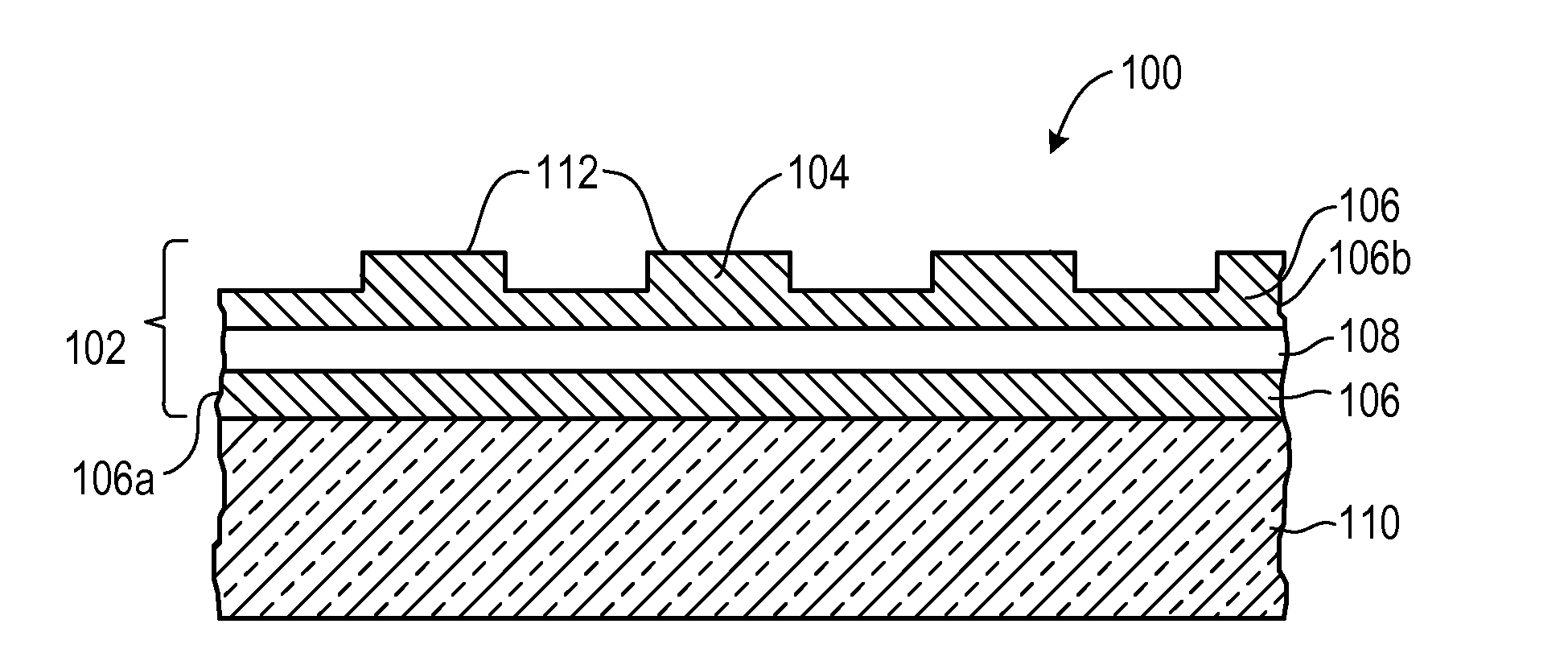
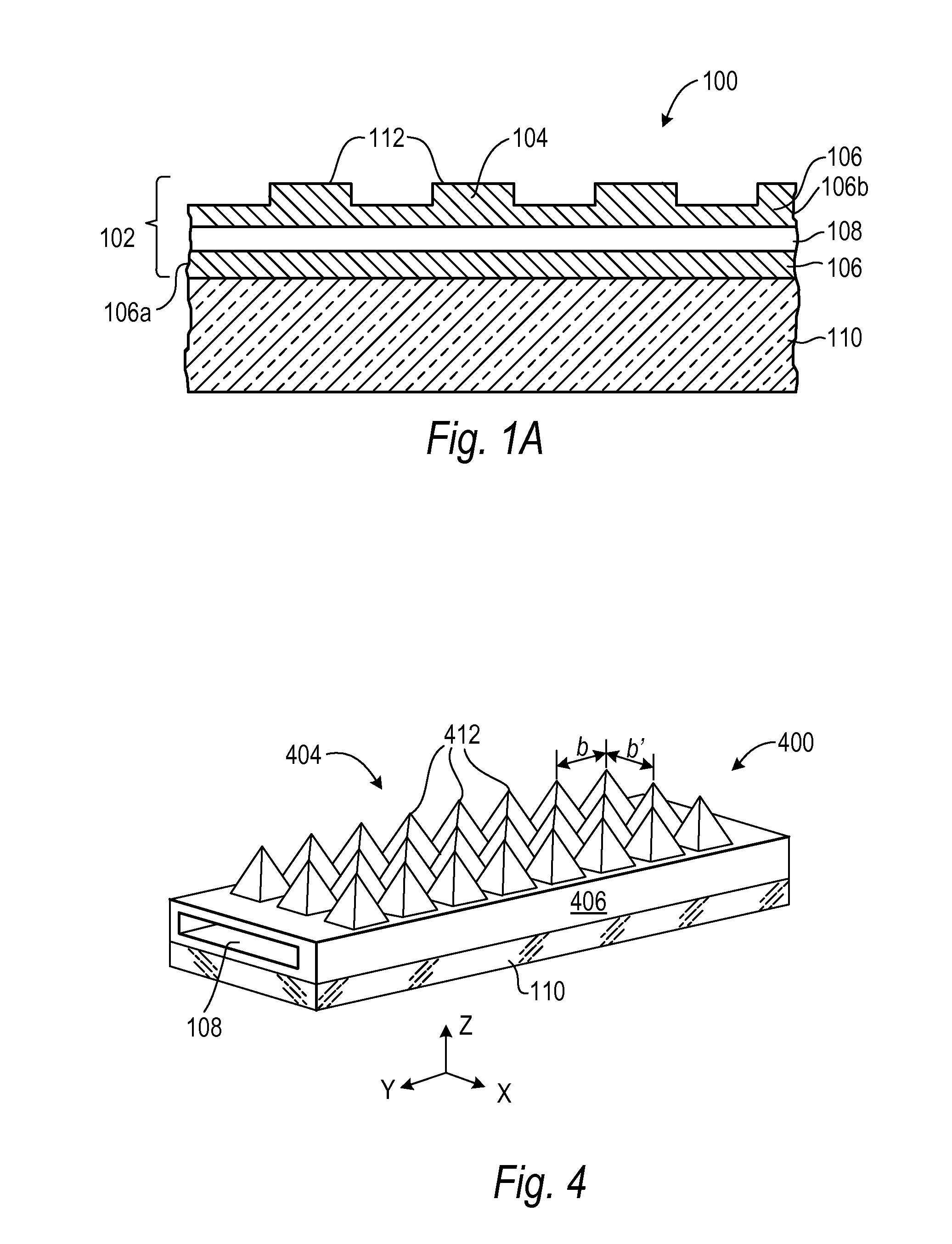
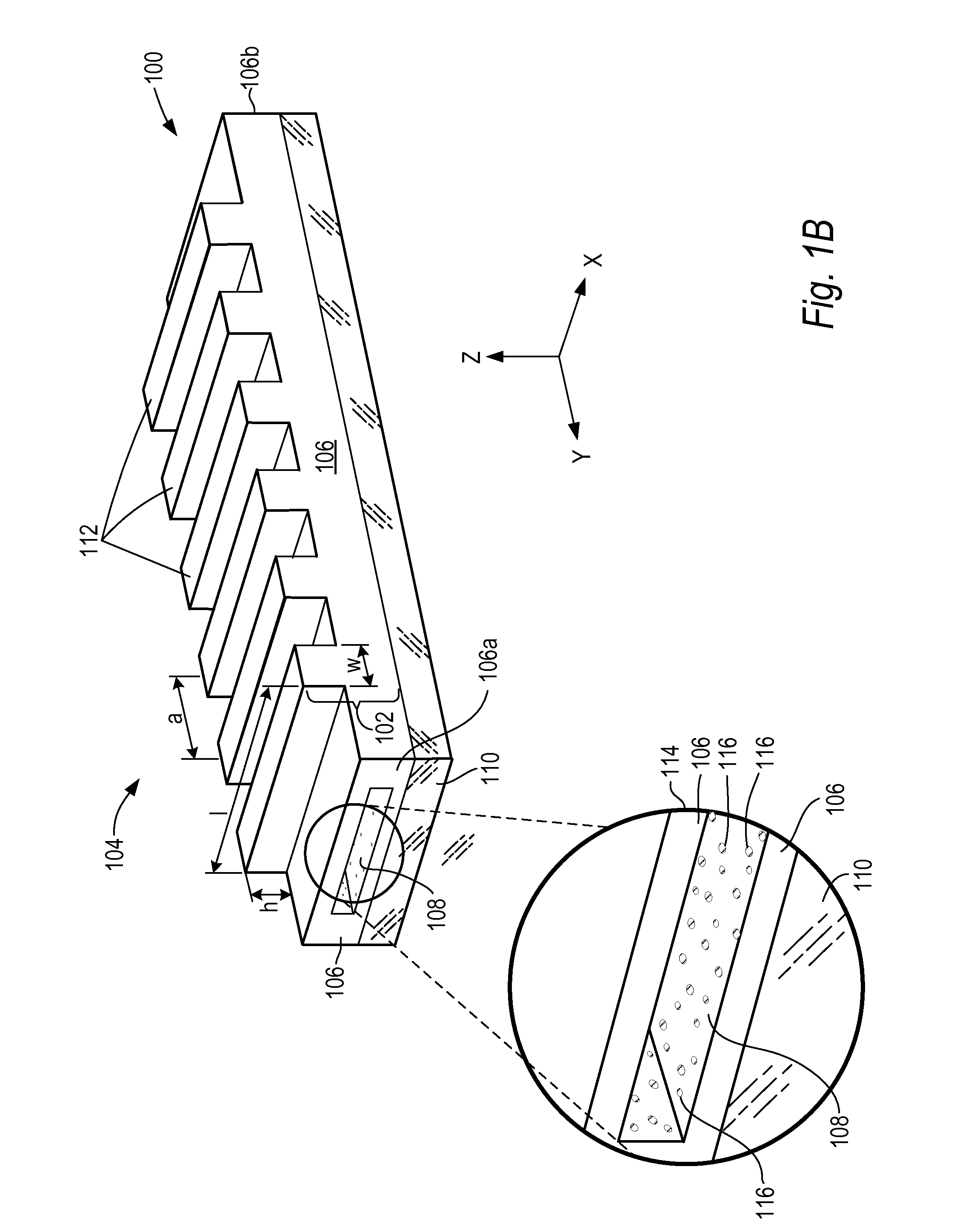
[0012]Reference is made now in detail to specific embodiments, which illustrates the best mode presently contemplated by the inventors for practicing the invention. Alternative embodiments are also briefly described as applicable.

[0013]Embodiments of the present invention are directed to systems for performing surface-enhanced Raman spectroscopy. The systems include a waveguide configured with an array of features to support guided-mode resonance for certain wavelengths of Raman-excitation light which increases the intensity of the electromagnetic field associated with the Raman-excitation light. In particular, wavelengths of the Raman-excitation light can be selected to generate a spectrum of Raman scattered light associated with particular analyte molecules, and the waveguide and array of features can be configured to provide guided-mode resonance for the Raman-excitation light. Portions of the outer surfaces of the array of features are coated with a Raman-active material that wh...


PUM


Abstract

A system for performing Raman spectroscopy comprises a waveguide layer configured with at least one array of features, the at least one array of features being configured to provide guided-mode resonance for at least one wavelength of electromagnetic radiation; and at least one fluid channel disposed in the waveguide layer. An analyte sensor comprises an electromagnetic radiation source configured to emit a range of wavelengths of electromagnetic radiation, the system for performing Raman spectroscopy, and at least one photodetector configured to detect Raman scattered light.

Description

STATEMENT OF GOVERNMENT INTEREST[0001]This invention has been made with Government support under Contract No. HR0011-09-3-0002, awarded by the Defense Advanced Research Projects Agency. The government has certain rights in the invention.TECHNICAL FIELD[0002]Embodiments of the present invention relate generally to systems for performing surface-enhanced Raman spectroscopy (SERS).BACKGROUND ART[0003]Raman spectroscopy is a spectroscopic technique used in condensed matter physics and chemistry to study vibrational, rotational, and other low-frequency modes in molecular systems. In a Raman spectroscopic experiment, an approximately monochromatic beam of light of a particular wavelength range passes through a sample of molecules and a spectrum of scattered light is emitted. The spectrum of wavelengths emitted from the molecule is called a “Raman spectrum” and the emitted light is called “Raman scattered light.” A Raman spectrum can reveal electronic, vibrational, and rotational energies ...

Claims


Application Information

Patent Timeline
IPC IPC(8): G01J3/44
CPCG01J3/44G02B2006/12107G02B2006/0325G01N21/658
Inventor WU, WEILI, JINGJINGXIA, QIANGFEIYANG, JIANHUA
Owner HEWLETT PACKARD DEV CO LP
Why Eureka
Try Eureka