
Techniques for wireless deployment

a wireless and wireless technology, applied in the field of wireless networks, can solve the problems of not being able to achieve “dial down, reducing the transmission power of access points, increasing the area, etc., and achieve the effect of reducing friendly interferen

Active Publication Date: 2011-05-19
GUEST TEK INTERACTIVE ENTERTAINMENT
View PDF13 Cites 21 Cited by
  • Summary
  • Abstract
  • Description
  • Claims
  • Application Information

AI Technical Summary

Benefits of technology

The solution effectively enhances geographic isolation and client location accuracy, even in challenging environments, by controlling association based on data rate and response time, and reducing interference through mixed polarizations, resulting in improved network performance and capacity.

Problems solved by technology

It is often not technically feasible to “dial down” the power of a transceiver to the point where it would continue to be useful in its intended area without transmitting beyond such barriers.
In addition, reducing the transmission power of access points increases areas of shadow (or signal detected from other access points), while decreasing the ratio of signal to noise.
These are both undesirable results in that they increase the likelihood that a client device might roam to an out-of-area access point.
However, closed environments such as building interiors and dense urban areas present conditions which seriously degrade the efficacy of such techniques.
That is, the combination of reflection, refraction, multi-path, and signal absorption in such environments form complex boundary conditions making position predictions based on signal strength and triangulation tricky and often inaccurate.
Methods to correct for these effects involve highly complex modeling and mapping of signal levels in the environment.
And unfortunately, this time consuming and expensive “correction” falls apart if even a small change occurs from the baseline mapping.
Unfortunately, such technologies are not always reliable inside buildings or in dense urban environments in that the reach of GPS equipment is limited by the attenuation caused by surrounding structures.
GPS solutions also involve the use of secondary equipment, increasing system costs and introducing an additional point of failure.

Method used


Image

  • Techniques for wireless deployment
  • Techniques for wireless deployment

Examples


Embodiment Construction

[0020]Reference will now be made in detail to specific embodiments of the invention including the best modes contemplated by the inventors for carrying out the invention. Examples of these specific embodiments are illustrated in the accompanying drawings. While the invention is described in conjunction with these specific embodiments, it will be understood that it is not intended to limit the invention to the described embodiments. On the contrary, it is intended to cover alternatives, modifications, and equivalents as may be included within the spirit and scope of the invention as defined by the appended claims. In the following description, specific details are set forth in order to provide a thorough understanding of the present invention. The present invention may be practiced without some or all of these specific details. In addition, well-known features may not have been described in detail to avoid unnecessarily obscuring the invention.

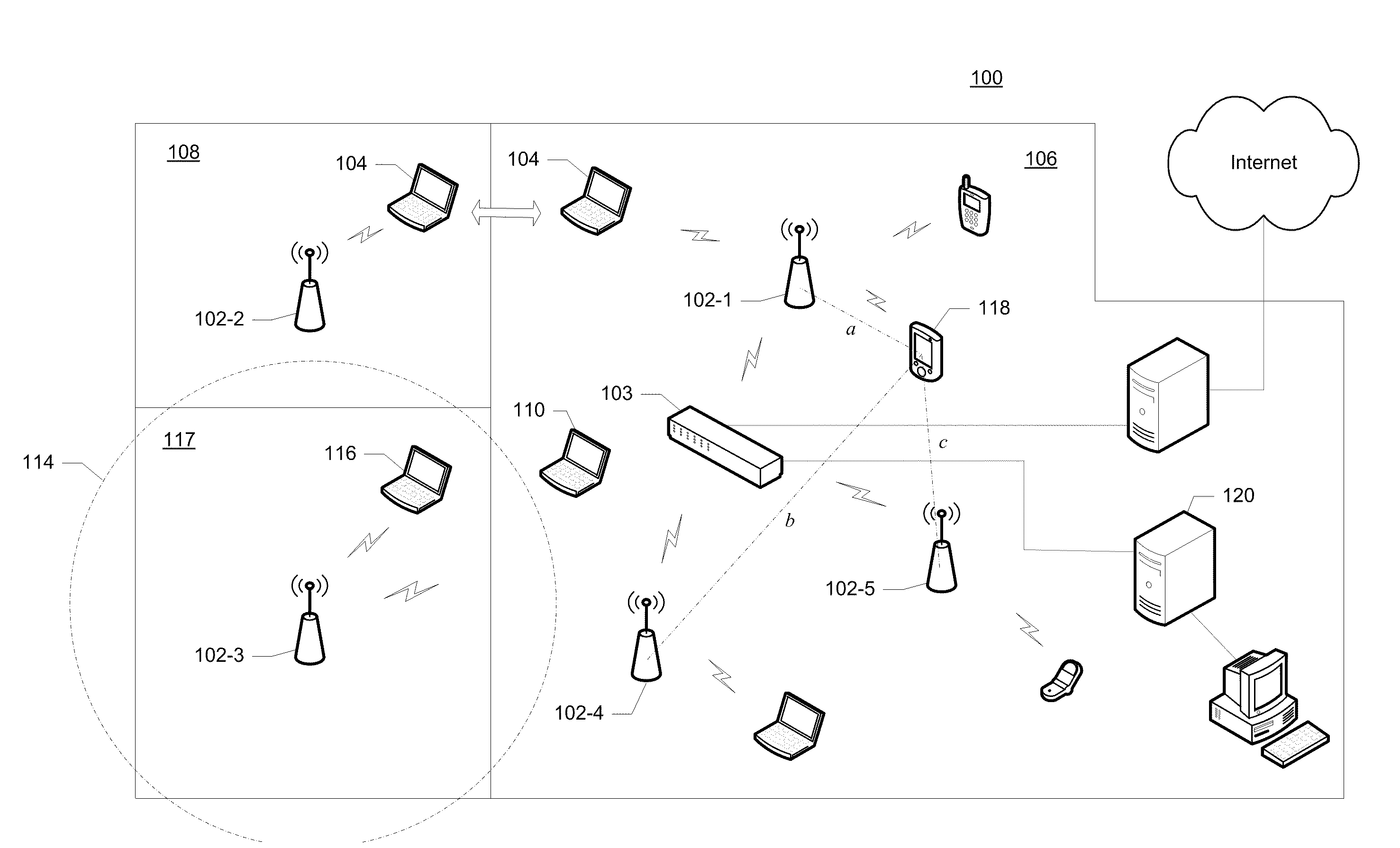
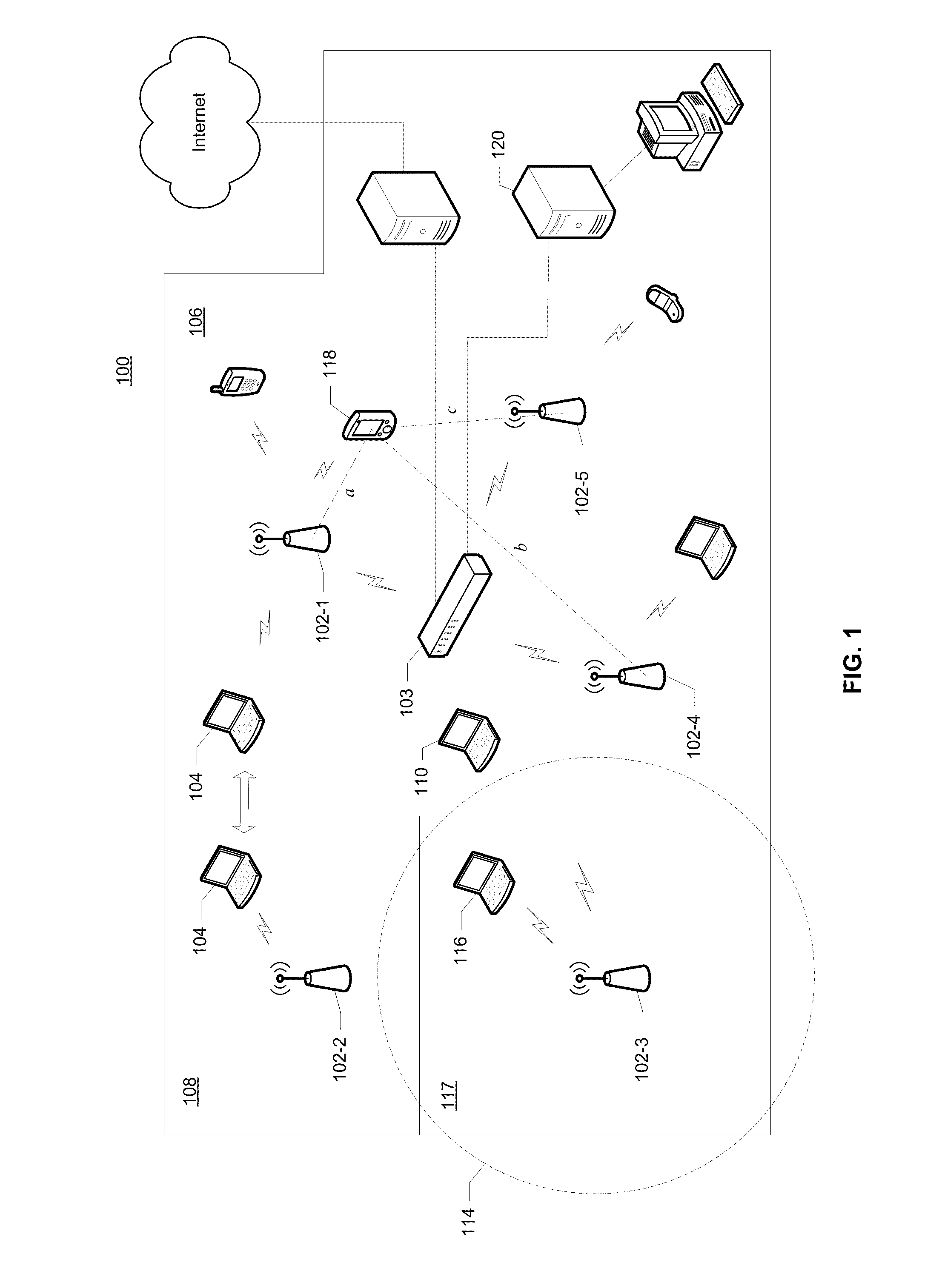
[0021]FIG. 1 is a simplified network dia...


PUM


Abstract

A variety of techniques are described in which wireless access points or base stations are deployed in wireless networks to achieve geographic isolation, i.e., distinct zones of operation having well-defined geographic boundaries, and increased overall capacity in an area having a high population of access and client devices.

Description

RELATED APPLICATION DATA[0001]The present application is a divisional of and claims priority under 35 U.S.C. 120 to U.S. patent application Ser. No. 11 / 534,190 for TECHNIQUES FOR WIRELESS DEPLOYMENT TO IMPROVE CAPACITY AND ACHIEVE GEOGRAPHIC ISOLATION filed on Sep. 21, 2006 (Attorney Docket No. STSNP009), which claims priority under 35 U.S.C. 119(e) to U.S. Provisional Patent Application No. 60 / 813,993 for TECHNIQUES FOR WIRELESS DEPLOYMENT TO MAXIMIZE CAPACITY AND GEOGRAPHIC ISOLATION filed on Jun. 14, 2006 (Attorney Docket No. STSNP009P), the entire disclosures of both which are incorporated herein by reference for all purposes.BACKGROUND OF THE INVENTION[0002]The present invention relates to wireless networks and, in particular, to a variety of techniques for the deployment and operation of access points in wireless networks to improve capacity and geographic isolation.[0003]Wireless networks typically employ egress / access devices, commonly referred to as access points, which for...

Claims


Application Information

Patent Timeline
Patent Type & Authority Applications(United States)
IPC IPC(8): H04W4/00H04W48/02
CPCH04W48/02H04W88/08H04B15/00H04W16/18H04W48/20H04W48/18H04B7/10
Inventor WELCH, JOHN THOMASSMITH, GARY L.DREWS, MICHAEL DAVIDMIDANI, WAEL R.
Owner GUEST TEK INTERACTIVE ENTERTAINMENT
Learn More