Eureka AIR delivers breakthrough ideas for toughest innovation challenges, trusted by R&D personnel around the world.

Method for selecting protective resistor value for a capacitor charging circuit which enables maximum energy transfer with minimal heat

a capacitor charging circuit and resistor value technology, applied in the direction of instruments, fault locations, material analysis, etc., can solve problems such as inability to solv

Inactive Publication Date: 2011-05-19
DAVIS JOHN MICHAEL +1
View PDF1 Cites 2 Cited by
  • Summary
  • Abstract
  • Description
  • Claims
  • Application Information

AI Technical Summary

Benefits of technology

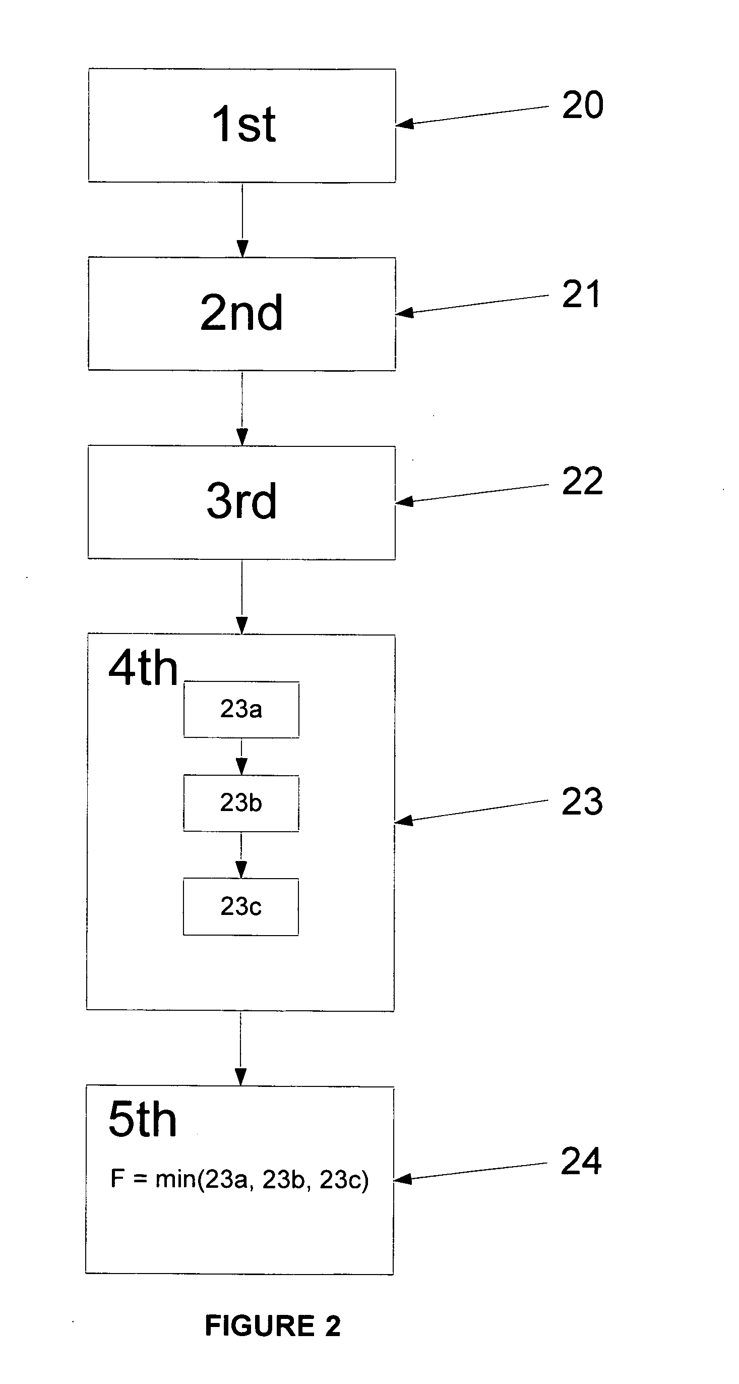
[0007]To avoid having to engage in testing all possible resistors which may be used as the means for limiting periodic inrush current to prevent component failures in a capacitor-charging circuit utilizing a non-linear power supply, and to maximize power transfer efficiency and limit cooling needs by selecting the least-strength resistor for the circuit, one determines the value of the desired protective resistance, and thus the choice of resistor, as follows.

Problems solved by technology

However, if the supply is non-linear, such as those designed for constant-current, high-voltage outputs, in general the problem can not be solved unless all of the supply circuits' parameters are known.

Method used


Image

  • Method for selecting protective resistor value for a capacitor charging circuit which enables maximum energy transfer with minimal heat
  • Method for selecting protective resistor value for a capacitor charging circuit which enables maximum energy transfer with minimal heat
  • Method for selecting protective resistor value for a capacitor charging circuit which enables maximum energy transfer with minimal heat

Examples


Embodiment Construction

[0016]There are two general means of providing high voltage to charge a capacitor. Either one uses an alternating current (AC) source (FIG. 1A, 2) with a rectifier circuit (FIG. 1A, 3), or a direct current power supply, which usually has an internal rectifier circuit such as a bridge rectifier (FIG. 1B, 9), as the direct source. In the simplest means a protective limiting resistor (FIG. 1A, 1; FIG. 1B, 8) is placed in series between the source (FIG. 1A, 2; FIG. 1B, 9) and the capacitor (FIG. 1A, 4; FIG. 1B, 7). In the example systems, the inductors (FIG. 1A, 5; FIG. 1B, 10) represent a load such as that of a pulsed electromagnetic field device, and the spark gaps (FIG. 1A, 6; FIG. 1B, 11) discharge the capacitors through the field coil inductors (FIG. 1A, 5; FIG. 1B, 10) when the capacitor charge is sufficient. In this case the protective resistors also function to protect the circuit elements when the inductor is generating a reverse voltage at the end of its discharge cycle.

[0017]...


PUM


Abstract

Electronic devices operate in an analog world and their circuitry is subject to non-linear environmental effects that can cause operational problems. Selecting components for a design for a capacitor-charging circuit that incorporates a current-limiting resistor and uses non-linear power supplies, either means having to test every possible combination of elements, and suffering a resultantcombinatorial explosion’ as complexity increases, or choosing to over-engineer against untested surprise failure points. Doing the latter in a cost-efficient manner through a min / max / log-set testing series also enables use of non-linear power supplies whose parameters are not known due to competitive or trade secret protective efforts by their manufacturers.

Description

BACKGROUND OF THE INVENTION[0001]A capacitor-charging circuit utilizing non-linear power supplies often requires a current-limiting resistor which can not be estimated by the solution of simple linear-circuit equations. Consequently, a process is required to determine the appropriate value of the current-limiting resistor which is both sufficient to limit the current to protect all heat-sensitive or current-sensitive components, and also not too stringent so as to maximize power transfer efficiency, thus also lowering cooling requirements for the final circuit.[0002]Power supplies for charging capacitors generally have a means of limiting periodic inrush current to prevent component failures. While there are many options for this, such as inductors, transistors, or varying supply voltages, the cheapest is often a resistor. The selection of the resistor for a linear power supply is simple: one solves the linear circuit equations for the greatest efficiency, or chooses the value provi...

Claims


Application Information

Patent Timeline
IPC IPC(8): G06Q10/00G01N25/00G01R31/02
CPCG01R31/00
Inventor DAVIS, JOHN MICHAELLESKE, LAWRENCE ALBERT
Owner DAVIS JOHN MICHAEL
Why Eureka
Eureka Blog
Learn More