
Multiple use wireless power systems

Inactive Publication Date: 2011-05-19
ACCESS BUSINESS GRP INT LLC
View PDF10 Cites 587 Cited by
  • Summary
  • Abstract
  • Description
  • Claims
  • Application Information

AI Technical Summary

Benefits of technology

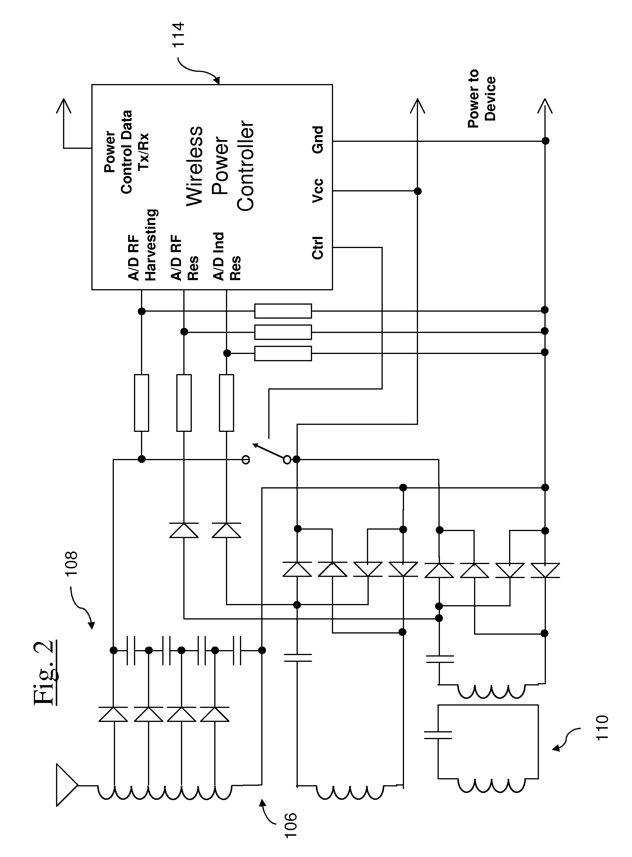
[0007]In a second aspect of the invention, a remote device includes a hybrid secondary that can be selectively configured for multiple uses. In one embodiment, the hybrid secondary may be selectively configured to either wirelessly receive power or to wirelessly communicate high speed data. In another embodiment, the hybrid secondary element may be selectively configured to either receive wireless power from a first wireless power supply or to receive wireless power from a second wireless power supply. The hybrid secondary occupies less space than two corresponding separate secondary elements. A hybrid secondary may be utilized within one area of the device to minimize size and incorporate several wireless power elements for best use of a space exposed to the outside world know as an aperture for wireless power. For example, where the remote device includes a housing having an aperture capable of passing wireless communication and wireless power, the hybrid secondary element may occupy a relatively smaller amount of physical space within the aperture of the remote device than two separate secondary elements would occupy in the aperture.

Problems solved by technology

Efforts to provide a universal wireless power solution are complicated by a variety of practical difficulties.
One difficulty is the lack of wireless power source infrastructure.
This issue is exacerbated by the incompatibility between some remote devices and some wireless power supply systems.
Currently, remote devices capable of receiving wireless power include a single wireless power receiving system and therefore are only capable of utilizing a subset of the wireless power infrastructure.
Unfortunately, it is likely impractical, for a variety of reasons, to include separate wireless power receiving systems for each type of desired wireless power.
One reason being that the available space in consumer electronics is shrinking.
Another reason is that including circuitry for each wireless power receiver such as a separate receiving element, separate communication system, separate rectifier, and separate controller adds to the cost and size of the remote device.
If multiple separate wireless power systems are used, the system would include several controllers, communication systems, and rectifiers increasing cost and size.
In addition to the complexities with a universal wireless power solution, there are also issues that arise due to the interactions between the remote device wireless power systems and remote device communication systems.
For example, certain wireless power sources can interfere or harm remote device communication systems in some circumstances.

Method used


Image

  • Multiple use wireless power systems
  • Multiple use wireless power systems
  • Multiple use wireless power systems

Examples


Embodiment Construction

I. Overview

[0027]A number of different aspects of a wireless power transfer system including a remote device capable of receiving wireless power are described below. There are a number of different features discussed including, but not limited to, a remote device with multiple wireless power inputs, a remote device with a hybrid secondary, a remote device with the ability to time slice communications, a remote device with the ability to wirelessly communicate with a far field wireless power source to enable a low power mode, and a remote device capable of determining whether a wireless hot spot is nearby.

II. Multiple Wireless Power Inputs

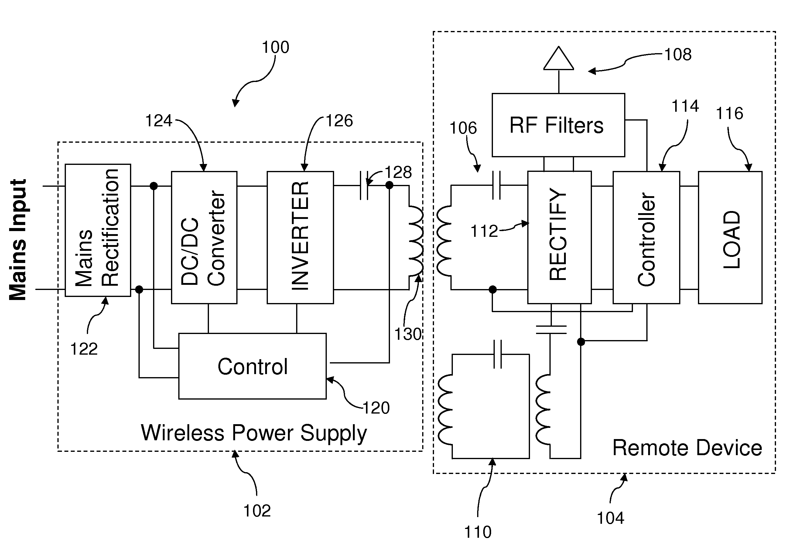
[0028]A wireless power supply system in accordance with an embodiment of one aspect of the present invention is shown in FIG. 1, and generally designated 100. The wireless power supply system 100 includes one or more wireless power supplies 102 and one or more remote devices 104. In this aspect of the invention, the remote device 104 is adapted to m...


PUM


Abstract

A wireless power system having at least one of a remote device with multiple wireless power inputs capable of receiving power from a different wireless power source, a remote device including a hybrid secondary that can be selectively configured for multiple uses, a remote device including a hybrid secondary, a far field wireless power source having a low power mode, a remote device having the capability of communicating with multiple different wireless power sources to indicate that a wireless power hot spot is nearby, a wireless power supply including multiple wireless power transmitters.

Description

BACKGROUND[0001]The widespread and continually growing use of portable electronic devices has led to a dramatic increase in the need for wireless power solutions. Wireless power supply systems eliminate the need for power cords and therefore eliminate the many inconveniences associated with power cords. For example, wireless power solutions can eliminate: (i) the need to retain and store a collection of power cords, (ii) the unsightly mess created by cords, (iii) the need to repeatedly physically connect and physically disconnect remote devices with cords, (iv) the need to carry power cords whenever power is required, such as recharging, and (v) the difficulty of identifying which of a collection of power cords is used for each device.[0002]There are a number of different types of wireless power supply systems. For example, many wireless power supply systems rely on inductive power transfer to convey electrical power without wires. One wireless power transfer system includes an indu...

Claims


Application Information

Patent Timeline
IPC IPC(8): H01F38/14H02J17/00
CPCH02J17/00H02J5/005H04B5/0087H04B5/0037H02J50/12H02J7/0068H02J50/20H02J50/80H02J50/40H04B5/263H04B5/79
Inventor BAARMAN, DAVID W.TAYLOR, JOSHUA B.SCHWANNECKE, JOSHUA K.MOLLEMA, SCOTT A.
Owner ACCESS BUSINESS GRP INT LLC
Learn More