
Zero-shock separation system

a separation system and zero-shock technology, applied in the direction of cosmonautic components, cosmonautic parts, cosmonautic vehicles, etc., can solve the problems of unfavorable shock transmission to the launch vehicle or payload, shock can be dangerous, pre-tensioning the belt, as it is conventionally done, and might prove to be a difficult task. , to achieve the effect of eliminating the difficult step and significantly simplifying the assembly/connection of the two bodies

Inactive Publication Date: 2011-05-19
RUAG SCHWEIZ AG
View PDF20 Cites 4 Cited by
  • Summary
  • Abstract
  • Description
  • Claims
  • Application Information

AI Technical Summary

Benefits of technology

[0010]In view of the drawbacks of the prior art, the objective of the present invention and the inventive solution summarized above, the present invention has the main advantage that the separation of the two bodies can be initiated in a smooth way, without a shock or sudden vibration and without the need of pre-tensioning the belt.
[0011]A further advantage of the present invention is that the assembly / connection of the two bodies is significantly simplified by elimination of the difficult step of pre-tensioning the belt.
[0012]An even further advantage of the present invention is that deformation of either of the two bodies due to the connection is excluded.

Problems solved by technology

However, when such a pre-tensioned belt is suddenly released / cut / disengaged, a strong, undesirable shock arises which is transmitted to the launch vehicle or payload.
Such a shock can be dangerous since it might affect the integrity or the trajectory of the launch vehicle or payload.
Furthermore, due to the size of the two bodies that needs to be releasably connected, the pre-tensioning of the belt, as it is conventionally done, might prove to be a difficult task.
Additionally, said tension in the belt might even cause an undesirable deformation of one of the two bodies.

Method used


Image

  • Zero-shock separation system
  • Zero-shock separation system
  • Zero-shock separation system

Examples


first embodiment

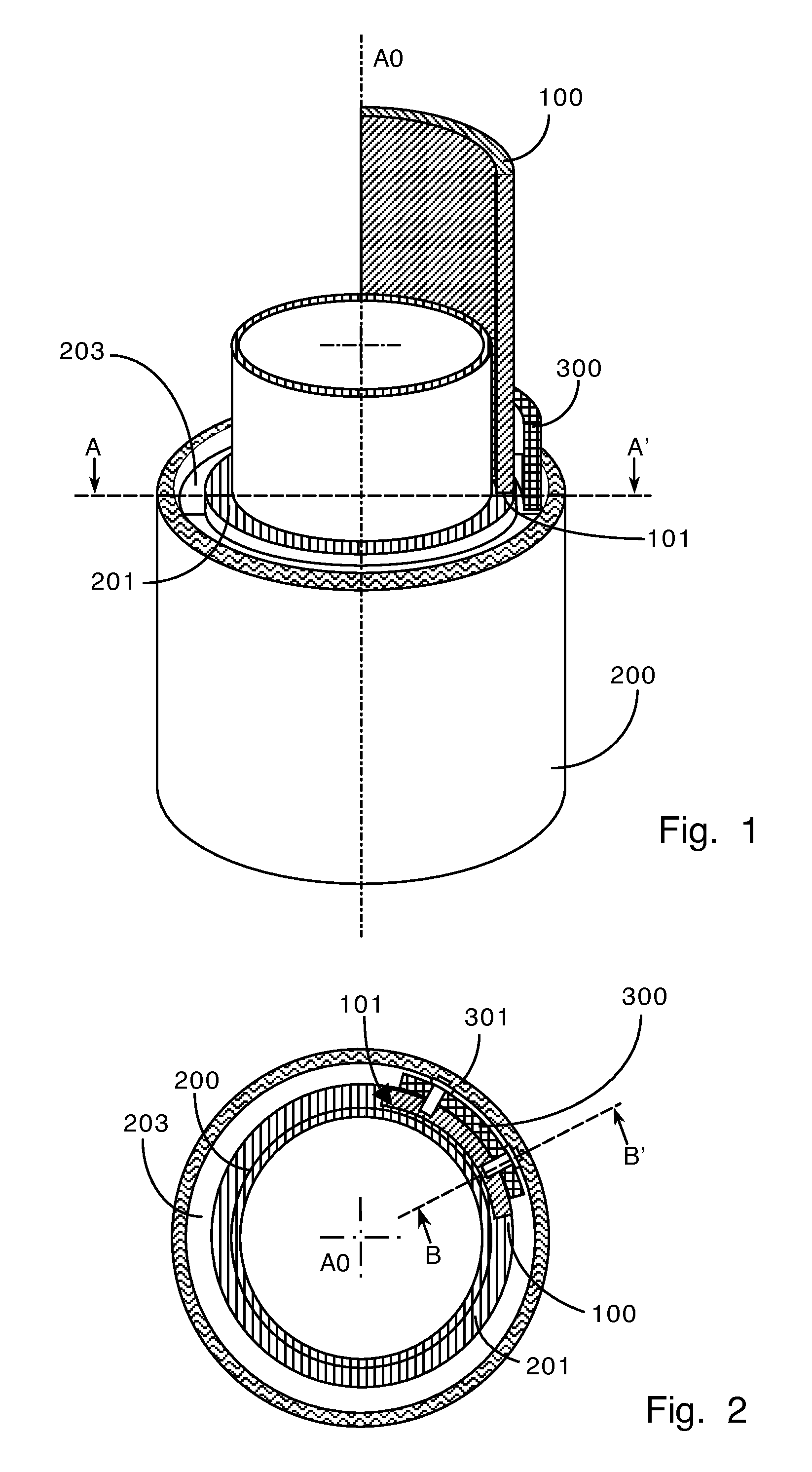
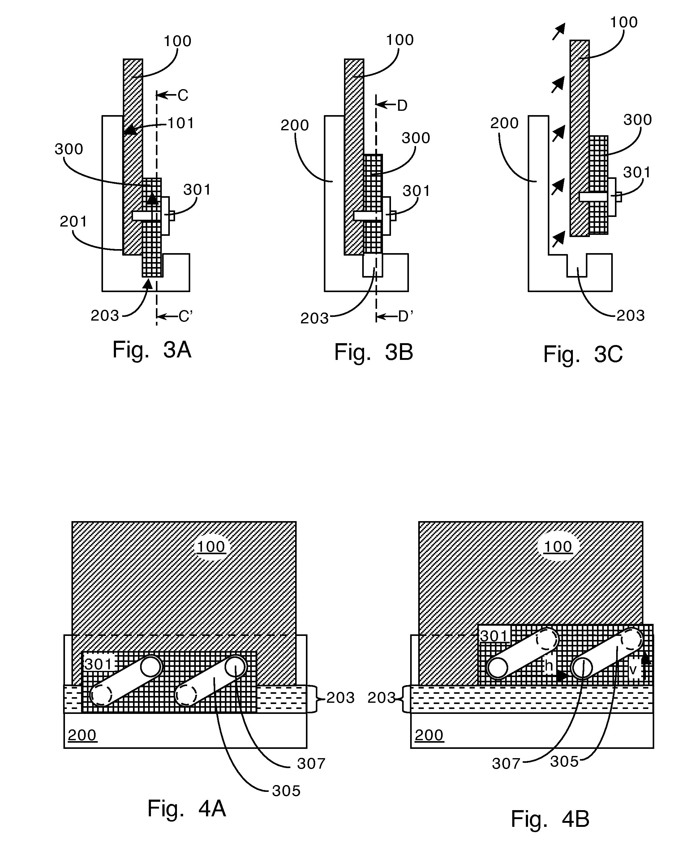
[0046]FIG. 1 shows a schematic perspective diagram, depicting a first embodiment the system of the present invention. A first body 100, here a circumferential quarter segment of a cylinder, with a first interface 101 is connected with a second interface 201 of a second body 200, here a cylindrical body. In this embodiment of the invention, the first body and the second body are coaxially arranged one around the other. The second interface 201 of the second body 200 is further provided with a circumferential trench 203 for axially receiving, preferably along a common longitudinal axis AO of the first body 100 and the second body 200, at least a circumferential portion of the belt 300. When said circumferential portion of the belt 300 is received in the circumferential trench 203, a radial fixation of the belt 300 with relation to the second body 200 is achieved. As seen on FIG. 1, the belt 300 surrounds, at least partially, the first body 100 and thus when it is radially fixed with r...

second embodiment

[0055]FIG. 6 represents a schematic cross-section of the second embodiment the system of the present invention along line E-E′ on FIG. 5 wherein multiple first bodies 100 are connected to the second body by a multitude of belts 300 and corresponding multitude of mechanical fixation means 301.

third embodiment

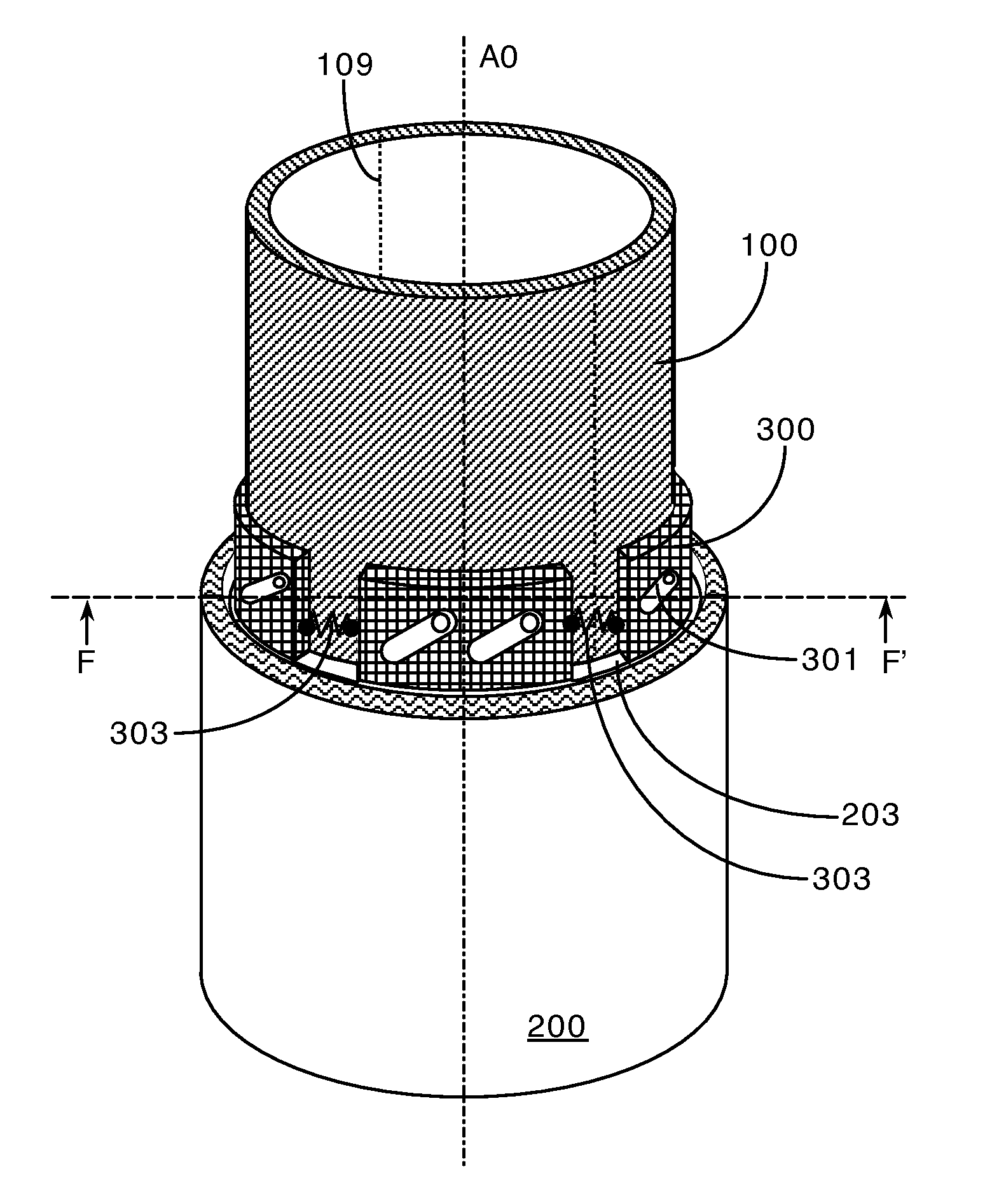
[0056]FIG. 7 is a schematic perspective diagram, depicting a third embodiment the system of the present invention, wherein a single first body 100 is connected to the second body 200 by a multitude of belts 300 and corresponding multitude of mechanical fixation means. Furthermore, FIG. 7 shows a pair of separation means 109 for allowing said first body 100 to separate into segments, two halves in the depicted examples. The separation means 109 are of the type known in the art, such as explosive charges, tension initiated separators, releasable joints, heat dissolved adhesives, etc.

[0057]Also shown on FIG. 7 are releasing mechanisms 303 provided for circumferentially connecting adjacent belts 300. These releasing mechanisms 303 have two functions:

[0058]initiating a circumferential shifting movement of the belt 300 in order to initiate the separation of the first body 100 from the second body 200;

[0059]in a preferred embodiment of the present invention, the releasing mechanisms 303 al...


PUM


Abstract

A system and corresponding method for a launch vehicle or spacecraft for releasably connecting a first body (100) with a first interface (101) and a second body (200) with a second matching interface (201), said system comprising: a belt (300) for releasably securing said first body (100) to said second body (200); a circumferential trench (203) at said second interface (201) for receiving said belt (300) in order to provide for a fixation of said belt (300) with relation to said second body (200); mechanical fixation means (301) attaching said belt (300) to said first body (100), said mechanical fixation means (301) being provided to enable a circumferential shifting movement of said belt (300) with respect to said circumference of said first body (100) in order to initiate a separation of the first body (100) from the second body (200), wherein said circumferential shifting movement induces a relative movement of said belt (300) with respect to said circumference of said first body (100) in order to remove said belt (300) from said trench (203), and wherein the system further comprising a releasing mechanism (303) causing said circumferential shifting movement.

Description

CROSS REFERENCE TO RELATED APPLICATIONS[0001]The present application claims the benefit of U.S. Provisional Patent Application 61 / 262,381 filed on Nov. 18, 2009, the disclosure of which is herein incorporated by reference.FIELD OF THE INVENTION[0002]The present invention relates to a zero-shock separation system for a launch vehicle or spacecraft for releasably connecting a first body with a second body, especially for connecting a payload fairing to the body of a launch vehicle or spacecraft.BACKGROUND OF THE INVENTION[0003]It is a common requirement for spacecrafts that two bodies, also called stages have to be releasably connected to each other. Due to the extreme conditions during takeoff and flight, these connections have to be extremely stable but at the same time a quick and reliable separation of the two bodies has to be ensured.[0004]In known separation systems, the first body, e.g. the payload fairing is connected to the second body, e.g. the body of the launch vehicle or ...

Claims


Application Information

Patent Timeline
Patent Type & Authority Applications(United States)
IPC IPC(8): B64G1/64
CPCB64G1/645B64G1/641
Inventor STRAUMANN, FRANZARX, RICHARD VON
Owner RUAG SCHWEIZ AG
Learn More