
Covered edge of hidden lamp strip of platform

A light belt and platform technology, which is applied to the anti-loss measures of lighting devices, lighting and heating equipment, semiconductor devices of light-emitting elements, etc., can solve the problems of insufficient edge sealing, inconvenient installation, and poor functionality of floor counters

Pending Publication Date: 2021-02-12
南京至美畅和科技会展股份有限公司
View PDF1 Cites 0 Cited by
  • Summary
  • Abstract
  • Description
  • Claims
  • Application Information

AI Technical Summary

Problems solved by technology

[0004] Although the base counter top in the above patent is applied to the edge wrapping of the platform, although it also has certain beneficial effects, there are still some shortcomings. The gap between the edge and the platform is too large, which is not beautiful enough, and it is not convenient to arrange the power cord and install the LED light group, and the functionality is poor

Method used


Image

  • Covered edge of hidden lamp strip of platform
  • Covered edge of hidden lamp strip of platform

Examples


Embodiment 1

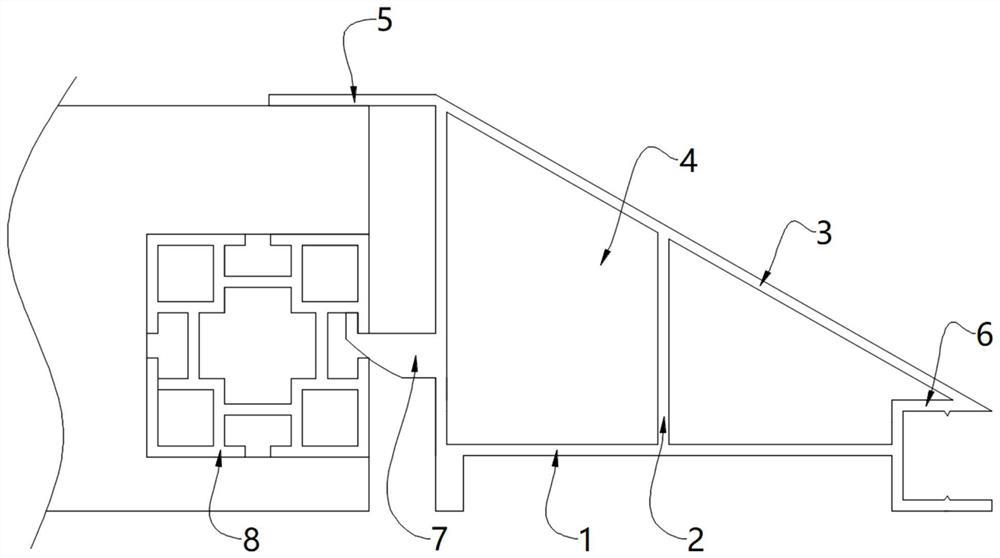
[0030] like figure 1 As shown in the figure, a floor concealed light belt wrapping includes a base plate 1, a support plate 2 is fixedly installed on the top of the base plate 1, a slant plate 3 is fixedly installed on the top of the support plate 2, and an extension plate is fixedly connected to the left end of the slant plate 3 4;

[0031] A connector 7 is fixedly installed on the left side of the support plate 2, an aluminum square channel 8 is fixedly installed on the outer wall of the connector 7, and a platform is fixedly installed on the left side of the aluminum square channel 8.

[0032] In this embodiment, the angle between the sloping plate 3 and the support plate 2 is 30 degrees, and the top of the sloping plate 3 is also laid with a floor, which is convenient for people to walk and is more beautiful.

[0033] In this embodiment, a cavity 4 is provided between the bottom plate 1, the support plate 2 and the slant plate 3, which can be used to arrange the power cor...

Embodiment 2

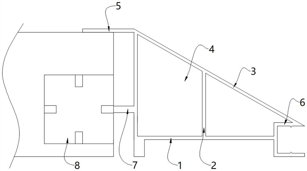
[0039] like figure 2 As shown in the figure, a floor concealed light belt wrapping includes a base plate 1, a support plate 2 is fixedly installed on the top of the base plate 1, a slant plate 3 is fixedly installed on the top of the support plate 2, and an extension plate is fixedly connected to the left end of the slant plate 3 4;

[0040] A connector 7 is fixedly installed on the left side of the support plate 2, an aluminum square channel 8 is fixedly installed on the outer wall of the connector 7, and a platform is fixedly installed on the left side of the aluminum square channel 8.

[0041] In this embodiment, the angle between the sloping plate 3 and the support plate 2 is 30 degrees, and the top of the sloping plate 3 is also laid with a floor, which is convenient for people to walk and is more beautiful.

[0042] In this embodiment, a cavity 4 is provided between the bottom plate 1, the support plate 2 and the slant plate 3, which can be used to arrange the power co...


PUM


Abstract

The invention relates to the technical field of platform covered edges, and discloses a platform hidden lamp strip covered edge which comprises a bottom plate, a supporting plate is fixedly installedat the top of the bottom plate, an inclined plate is fixedly installed at the top of the supporting plate, an extension plate is fixedly connected to the left end of the inclined plate, and a connecting piece is fixedly installed on the left side of the supporting plate. An aluminum square tube is fixedly installed on the outer wall of the connecting piece, the whole covered edge can be installedon the aluminum square tube through the connecting piece, installation is easier and more convenient, the extension plate at the left end of the inclined plate can be erected on a platform, connectionis tighter, a splicing gap between the extension plate and the platform can be shielded, and therefore the optimal display effect is achieved. Cavities are formed among the bottom plate, the supporting plate and the inclined plate and can be used for arranging power lines, so that the power lines are not prone to being treaded and pressed, safety is higher, dangerous accidents such as electric leakage and electric shock are prevented, the LED lamp set is fixedly installed on the inner wall of the installation groove plate, the periphery of the covered edge can have the light-emitting effect,and the covered edge is more attractive.

Description

technical field [0001] The invention relates to the technical field of platform wrapping, in particular to a platform wrapping concealed light belt. Background technique [0002] In exhibitions, festivals and other activities, it is often necessary to build exhibition platforms on the ground to facilitate the development of activities. After the platform is built, for the beauty of the platform and the convenience of getting on and off the platform, a platform wrapping is usually set at the edge of the platform. [0003] The Chinese patent announcement number is: CN202312208U invention patent, which discloses a base cabinet table top with wrapping edges. It prolongs its service life, and can choose the color of the edge according to the needs, and has an aesthetic effect, so it has good practicability and wide market value. [0004] Although the base counter top in the above patent is applied to the edge wrapping of the platform, although it also has certain beneficial eff...

Claims


Application Information

Patent Timeline
IPC IPC(8): F21S8/00F21V33/00F21V23/00F21V19/00F21V15/01F21V17/10F21Y115/10
CPCF21S8/00F21V15/01F21V17/10F21V19/001F21V23/001F21V33/00F21Y2115/10
Inventor 吴晓军
Owner 南京至美畅和科技会展股份有限公司
Learn More