
Feed device with two rotary valves which are variable independently of each other

a technology of rotary valves and feed devices, which is applied in the direction of presses, grain treatment, manufacturing tools, etc., can solve the problems of high-pressure roller press overload and start to vibra

Inactive Publication Date: 2011-05-19
KHD HUMBOLDT WEDAG GMBH
View PDF8 Cites 5 Cited by
  • Summary
  • Abstract
  • Description
  • Claims
  • Application Information

AI Technical Summary

Benefits of technology

[0007]The object of the invention is to improve the function of the feed device in terms of the feed characteristics of the high-pressure roller press in its entirety and in terms of an even distribution of the drive power to different drive motors of the high-pressure roller press.
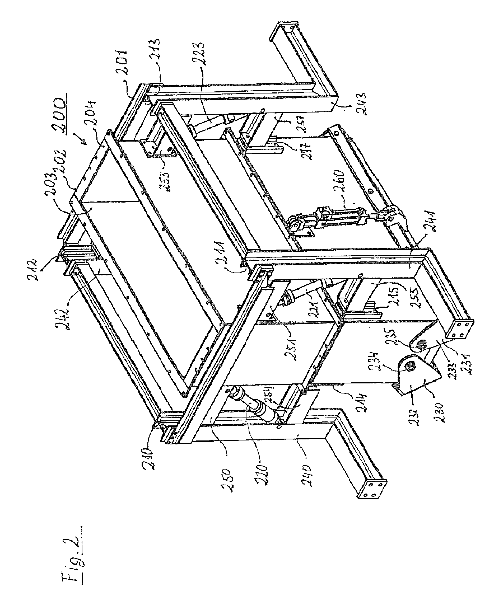
[0009]Through the presence of at least two rotary valves, the feed device according to the invention allows adaptation to the varying requirements associated with the changing material properties of the feed material. It is thus possible to open and close the two rotary valves in symmetry in order thus to deliver a specific average total quantity per unit of time to the high-pressure roller press. Apart from this pure metering function, as a result of uniform opening around the center point of the feed device centrally above the roller nip of the high-pressure roller press, it is also possible to set the two rotary valves such that the center of opening between the at least two rotary valves is not arranged over the center of the roller nip, but is laterally offset thereto. It is hereby possible to vary not only the feed quantity, but also the exact delivery location. Specifically when the high-pressure roller press is started, this adjustment facility makes it easier to quickly reach the optimal operating state of the high-pressure roller press.
[0010]In one embodiment of the invention it is provided that the rotary valves are disposed on a shaft which is variable in height above the roller nip. The height-variability of the shaft, and hence also of the rotary valves, allows the bulk material cone leaving the feed device to be altered, within the limits of the natural bulk material cone that is predefined by the material properties of the feed material, on the one hand, by the mechanical movement of the bulk material cone from below and, on the other hand, by the rotating rollers of the high-pressure roller press. This variation facility, too, offers operating staff the opportunity to configure the optimal bulk material cone over the roller nip, so that a low-vibration operation with minimum possible energy consumption is possible.
[0011]In order to protect the shaft from excessive abrasion by ores or by non-comminuted cement clinker, in a further embodiment of the invention it is provided that the shaft is provided with an exchangeable inner lining as an abrasion protection. If the abrasion protection is eroded during operation, then the inner lining, which the lining and shaft lie one inside the other like two stacked together shafts, can be exchanged with comparatively little effort, and thus the shaft, which in addition to its shaft function must also deflect mechanical forces, can be protected from destruction.
[0012]According to the invention, the rotary valves are adjustable by means of a hydraulic system. Although it is also possible to choose another type of drive, hydraulic operation has proved advantageous because it is robust enough to withstand the rough conditions associated with the grinding of brittle material. It is here provided that the hydraulic system acts on one side upon the rotary valve, and with the other side of the telescopic hydraulic system upon the shaft, which shaft can be varied in height above the roller nip. Insofar as the supply lines for the hydraulic systems are long enough and flexible, it is possible to raise and lower the shaft which is variable in height above the roller nip, in which case the hydraulic systems for the opening and closure of the rotary valves travel along with the shaft.
[0016]Since the shaft is raised and relowered within the rack system by the hydraulic system, it is advantageous if the shaft is supported by a linear bearing within the rack system and, when raised and relowered, slides up and down within the linear bearing. The linear bearing consists in its simplest form of a U-profile, which is disposed on the shaft with its opening facing outward and in which a horizontal stay reaching from the rack system to the linear bearing engages; the stay is here fixedly connected to the rack system. The converse arrangement, too, is possible, in which the stay is fastened to the shaft and engages in a linear bearing on the rack system.

Problems solved by technology

If, on the other hand, too large a quantity is poured onto the roller nip, it can happen that the high-pressure roller press is overloaded and starts to vibrate.

Method used


Image

  • Feed device with two rotary valves which are variable independently of each other
  • Feed device with two rotary valves which are variable independently of each other
  • Feed device with two rotary valves which are variable independently of each other

Examples


Embodiment Construction

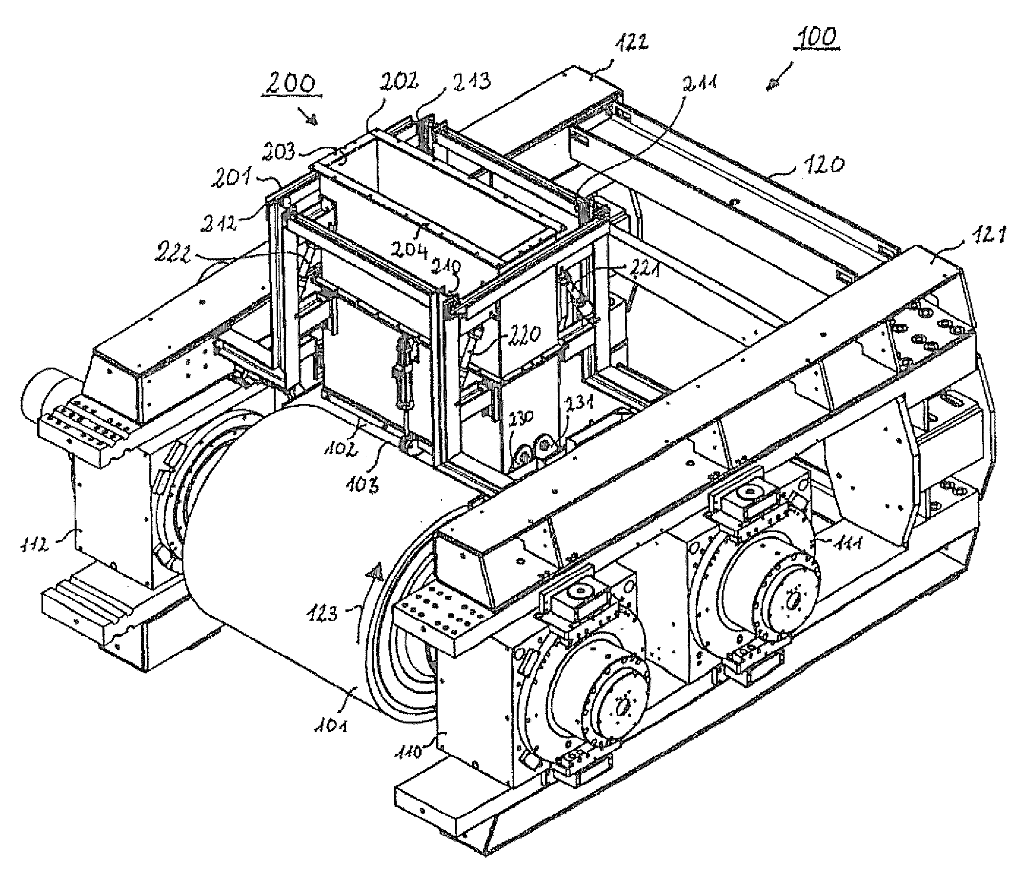
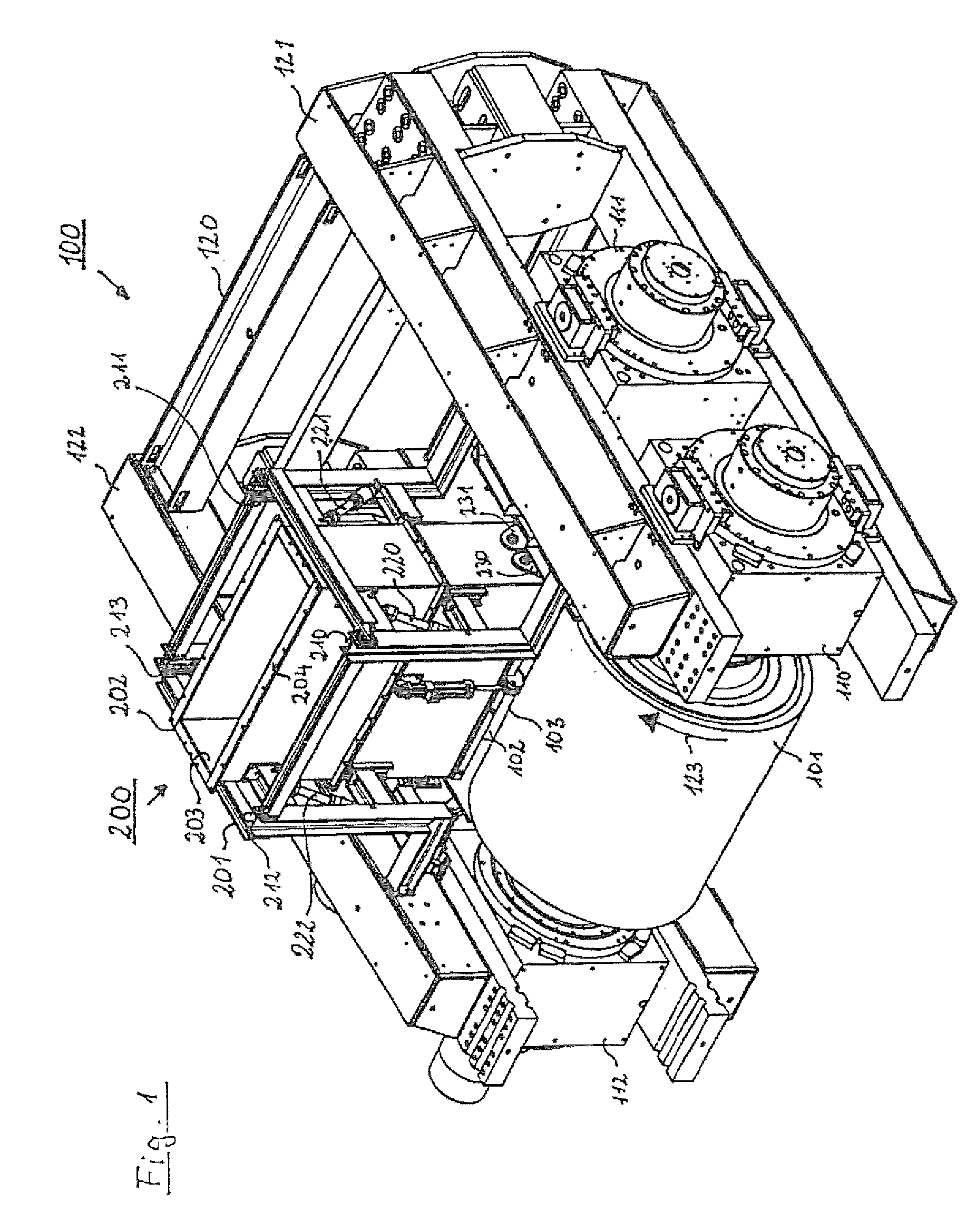
[0023]In FIG. 1 there is configured a high-pressure roller press 100, on which a feed device 200 according to the present invention is mounted. The high-pressure roller press 100 has two rollers 101 and 102, in this view the roller 102 being for the most part concealed, and the two rollers 101 and 102 form a roller nip 103 through which the feed material 104 (not represented here) passes, wherein the feed material 104, during passage through the roller nip 103, is comminuted by the high pressure prevailing therein. In order to be able to absorb the high forces which arise in the course of the high-pressure comminution, the rollers 101 and 102 are mounted in large-sized bearings 110, 111, 112 and in the bearing 113 (visible in FIG. 5) which in FIG. 1 is concealed by the drawing view, and the bearings 110, 111, 112 and 113 are for their part accommodated in a machine frame 120, which slidingly fixes the four bearings 110, 111, 112 and 113. Slidingly fixes means that the two rollers 10...


PUM


Abstract

A feed device for a high-pressure roller press for the high-pressure comminution of material to be ground, the feed device feeding the material to be ground in a controlled manner into the roller nip between two rollers of the high-pressure roller press. The feed device has at least two rotary valves, the position of which is variable independently of each other. In a refinement of the invention, the feed device also has a shaft which is variable in height above the roller nip. By means of the rotary valves which are variable independently of each other and by means of the height-variable shaft, the feeding behavior of the feed device can be varied during the starting of the high-pressure roller press and during the operation of the high-pressure roller press in order thereby to prevent the high-pressure roller press from vibrating and to ensure optimum operation of the high-pressure roller press.

Description

BACKGROUND OF THE INVENTION[0001]The invention relates to a feed device for a high-pressure roller press for the high-pressure comminution of grinding stock, said feed device delivering the grinding stock in a controlled manner into the roller nip between two rollers of the high-pressure roller press.[0002]For the comminution of brittle grinding stock, Schönert in 1977 proposed in German Auslegeschrift DE 27 08 053 not to comminute the grinding stock in traditional fashion, but firstly, through the application of high pressure in a roller nip, to press the grinding stock into flakes, whereupon the structure of the grinding stock ruptures. In a further step, the flakes emerging from the roller nip can be broken down into their individual component parts using comparatively little energy. The high-pressure pressing in the roller nip and the subsequent disagglomeration of the pressed flakes demands less energy for the comminution per unit of mass of grinding stock than does a conventio...

Claims


Application Information

Patent Timeline
IPC IPC(8): B02C23/02
CPCB30B15/04B02C4/286
Inventor NICKEL, ALEX
Owner KHD HUMBOLDT WEDAG GMBH
Learn More