
Techniques to control uplink power

a technology of uplink power and transmitter power, applied in the direction of power management, wireless communication, electromagnetic wave modulation, etc., can solve the problems of reducing the link performance of the other mobile stations, increasing interference to neighboring mobile stations,

Inactive Publication Date: 2011-05-12
INTEL CORP
View PDF8 Cites 88 Cited by
  • Summary
  • Abstract
  • Description
  • Claims
  • Application Information

AI Technical Summary

Problems solved by technology

Increasing transmission power of one mobile station enjoys the increase of its link performance but increases interferences to other mobile stations of neighboring base stations because they use the same channel.
This results in decreased link performance of the other mobile stations.

Method used


Image

  • Techniques to control uplink power
  • Techniques to control uplink power
  • Techniques to control uplink power

Examples


Embodiment Construction

[0013]Reference throughout this specification to “one embodiment” or “an embodiment” means that a particular feature, structure, or characteristic described in connection with the embodiment is included in at least one embodiment of the present invention. Thus, the appearances of the phrase “in one embodiment” or “an embodiment” in various places throughout this specification are not necessarily all referring to the same embodiment. Furthermore, the particular features, structures, or characteristics may be combined in one or more embodiments.

[0014]Embodiments of the invention may be used in a variety of applications. Some embodiments of the invention may be used in conjunction with various devices and systems, for example, a transmitter, a receiver, a transceiver, a transmitter-receiver, a wireless communication station, a wireless communication device, a wireless Access Point (AP), a modem, a wireless modem, a Personal Computer (PC), a desktop computer, a mobile computer, a laptop...


PUM


Abstract

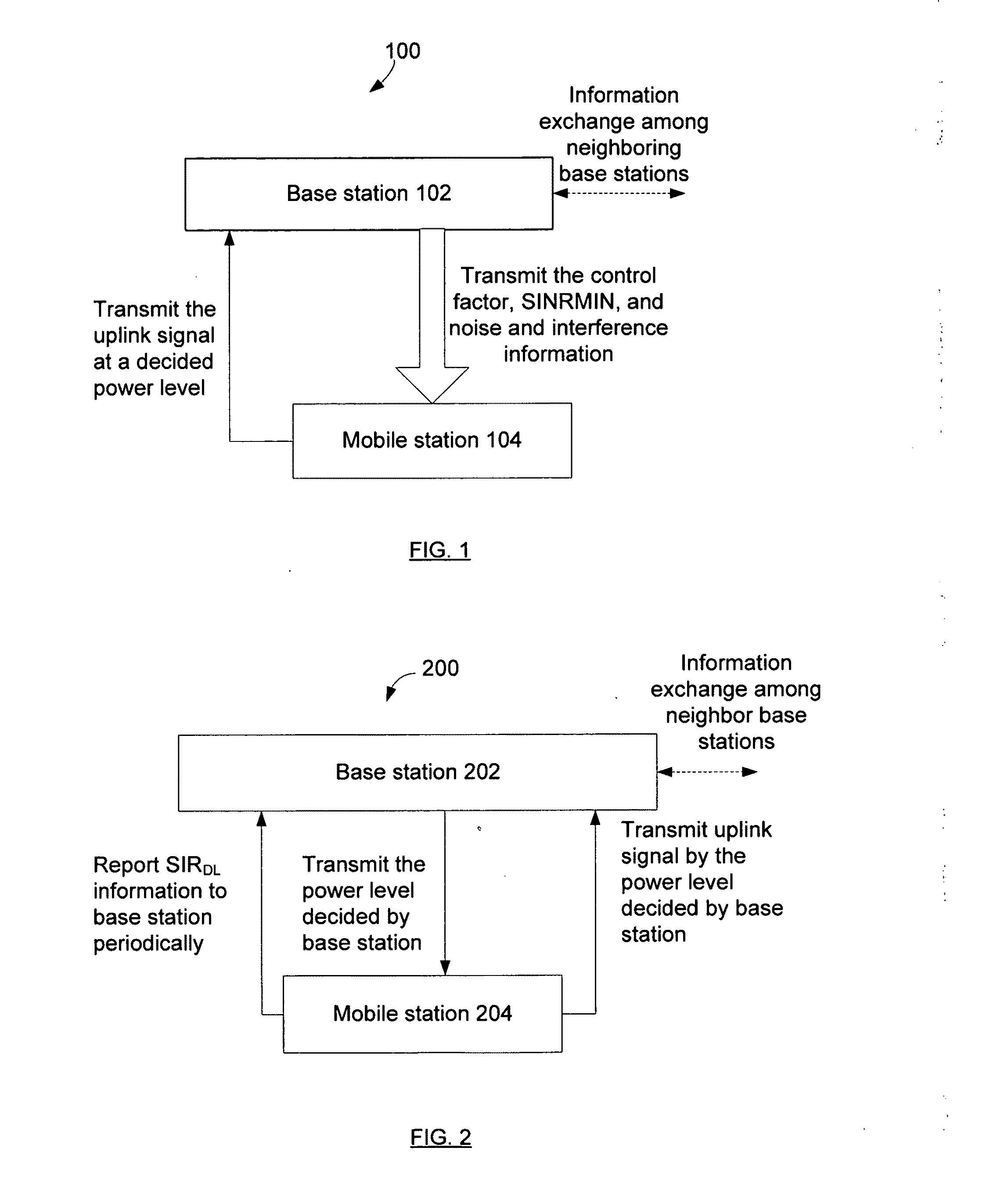
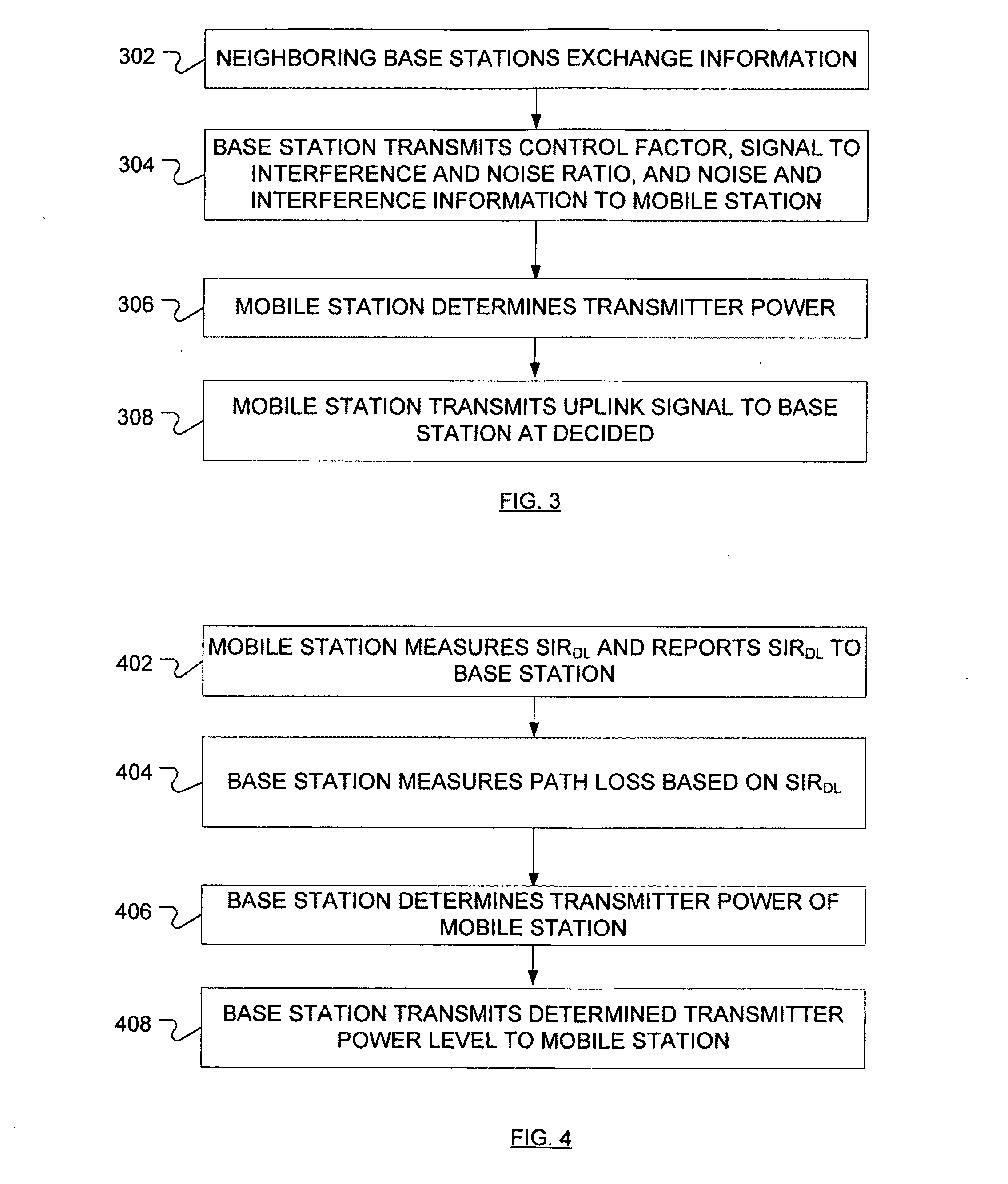
Techniques are described that provide uplink power control techniques that can support different uplink multi-input multi-output (MIMO) transmission schemes. Open and closed loop power control schemes can be used to prescribe the power level of the mobile station.

Description

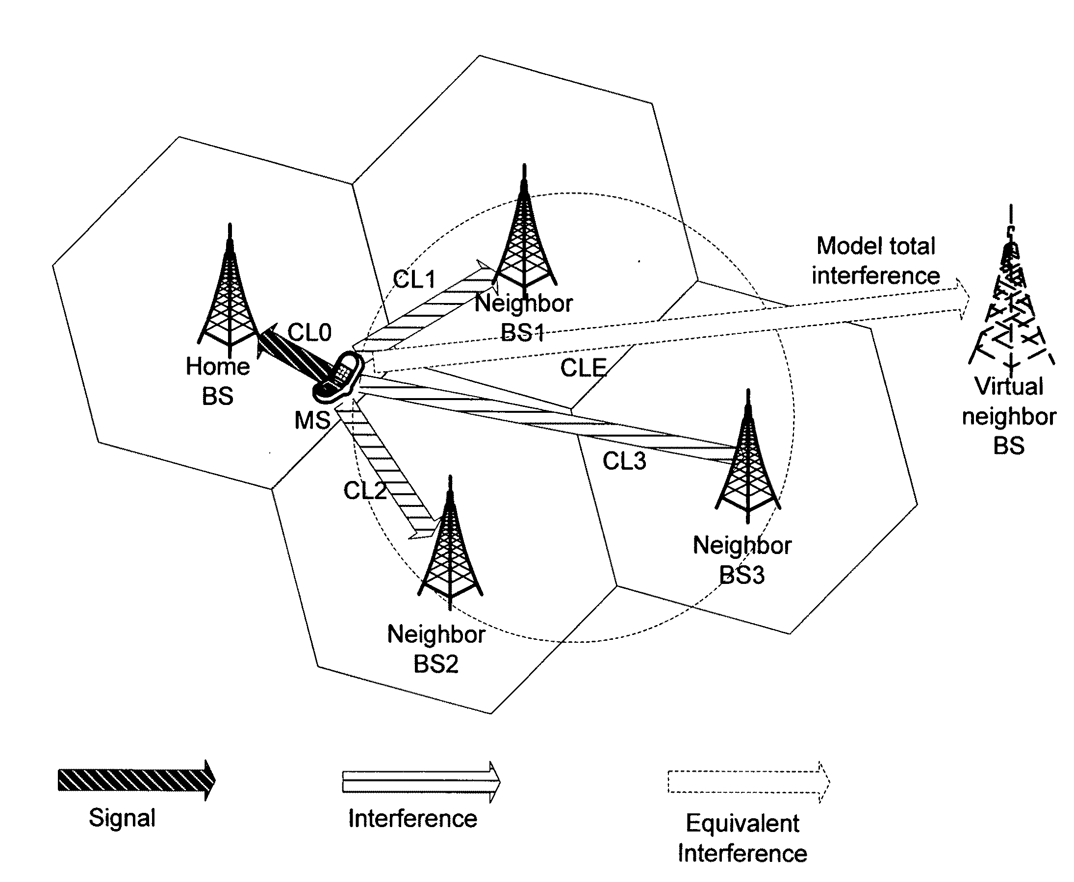
FIELD [0001]The subject matter disclosed herein relates generally to techniques to determine transmitter power of a wireless signal.RELATED ART [0002]In wireless networks, OFDM / OFDMA with multi-input multi-output (MIMO) is an important technology for next-generation mobile broadband networks. Uplink power control is an extremely important component of MIMO OFDM / OFDMA. Uplink power control involves controlling the transmit power level to balance the link performance and terminal battery power and to reduce the inter-base station uplink co-channel interference. Increasing transmission power of one mobile station enjoys the increase of its link performance but increases interferences to other mobile stations of neighboring base stations because they use the same channel. This results in decreased link performance of the other mobile stations. Therefore, in deciding uplink power level, it is important to balance the performance of a particular link with interference to the other base st...

Claims


Application Information

Patent Timeline
Patent Type & Authority Applications(United States)
IPC IPC(8): H04W52/04H04W72/04H04B15/00H04W72/54
CPCH04W52/241H04W52/242H04W52/243H04W72/082H04W52/247H04W72/0406H04W52/246H04W72/20H04W72/541H04W52/24H04W52/42H04W52/06
Inventor YANG, RONGZHENPAPATHANASSIOU, APOSTOLOSYIN, HUJUNCHOI, YANG-SEOKGUAN, WEI
Owner INTEL CORP
Learn More