
Image generation device with optimized dose control

Active Publication Date: 2011-05-12
KONINKLIJKE PHILIPS ELECTRONICS NV
View PDF9 Cites 21 Cited by
  • Summary
  • Abstract
  • Description
  • Claims
  • Application Information

AI Technical Summary

Benefits of technology

[0004]It is an object of the present invention to provide an image generation device, an image generation method and a computer program for generating an image from measured data, which provide enhanced dose control.
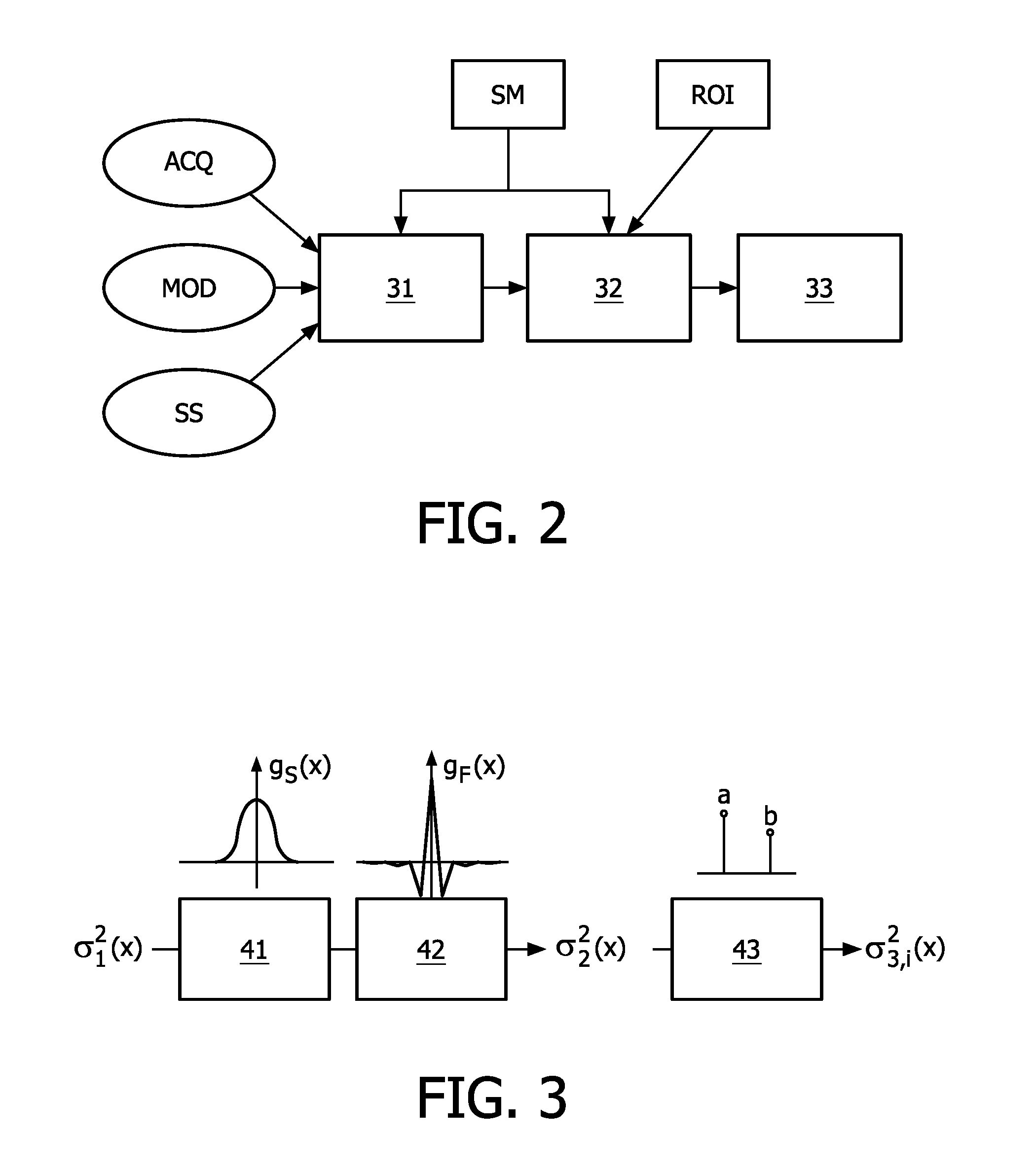
[0008]The invention is based on the idea that noise is determined in individual voxels of the reconstructed volume on the basis of noise distributions in the projections. Using the projection noise distributions the optimum dose profile can be calculated on the basis of the noise propagation. The signal-to-noise ratio is specifically improved for the selected region of interest of the reconstructed volume. This solution offers multiple advantages including higher image quality by using the same dose, reduction of dose by maintaining image quality, and homogenization of noise induced artifact patterns, especially for asymmetric patient geometries.
[0016]It is preferred that the dose profile is determined based on at least one of a reduced spatial resolution lower than a final resolution of said image and a simplified noise propagation algorithm, to thereby speed up determination of the optimal dose modulation.

Problems solved by technology

However, these techniques account for a large fraction of the collective applied dose in radiology and therefore, the applied patient dose has become a critical issue.

Method used


Image

  • Image generation device with optimized dose control
  • Image generation device with optimized dose control
  • Image generation device with optimized dose control

Examples


Embodiment Construction

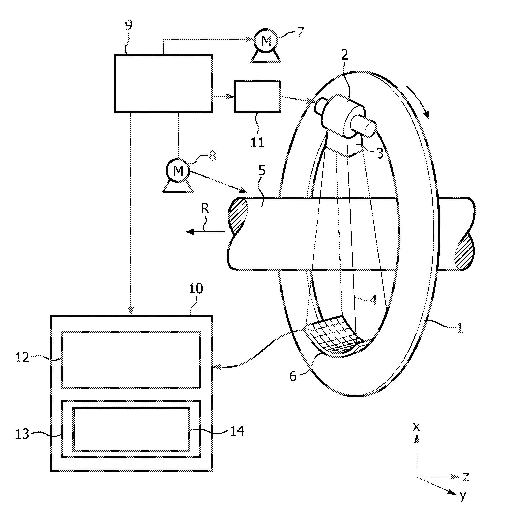
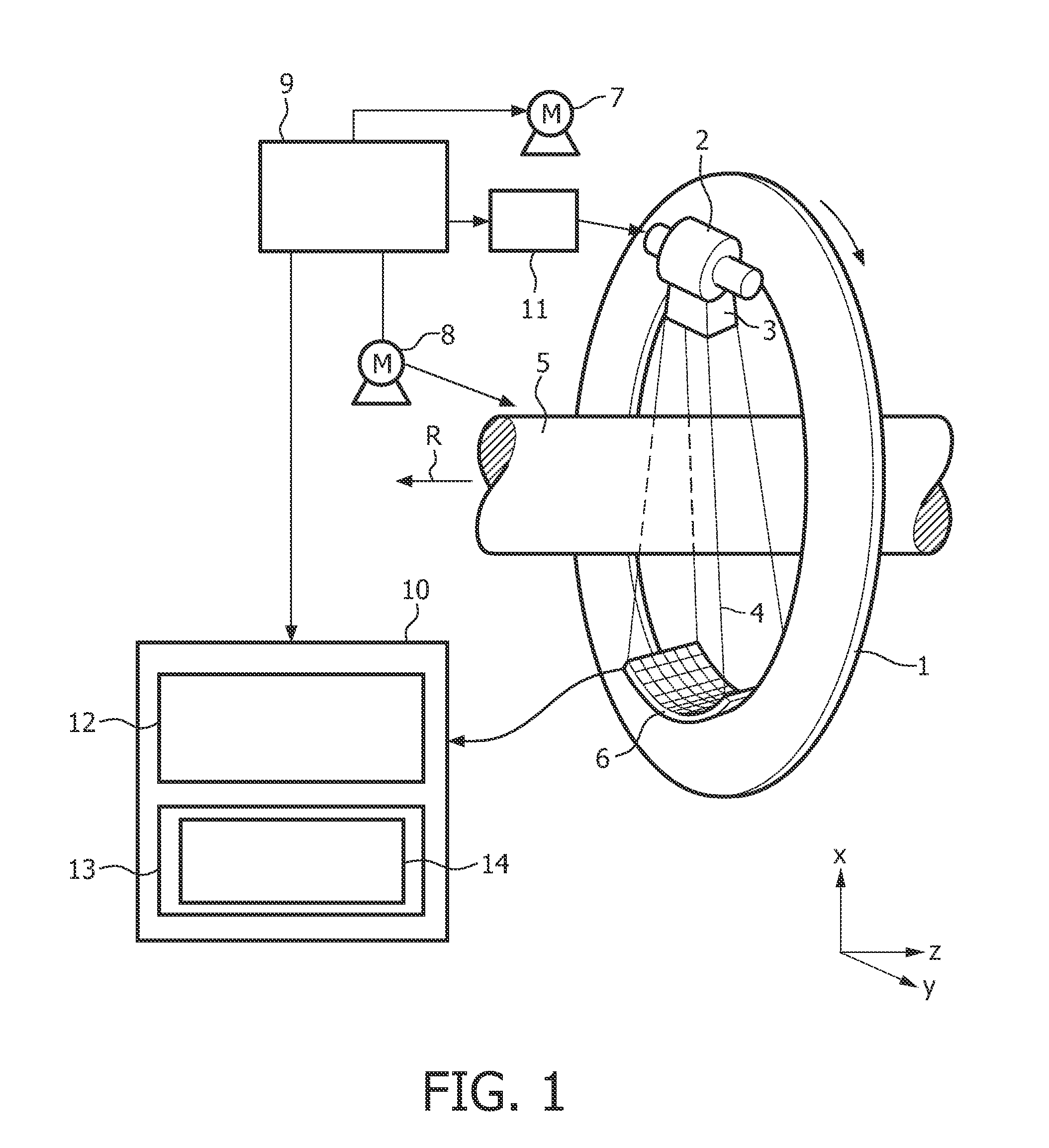
[0035]FIG. 1 shows schematically and exemplarily an imaging system being a computed tomography system. The computed tomography system includes a gantry 1 which is capable of rotation about a rotational axis R which extends parallel to the z direction. A radiation source 2, which is, in this embodiment, an X-ray tube, is mounted on the gantry 1. The radiation source 2 is provided with a collimator 3, which forms, in this embodiment, a conical radiation beam 4 from the radiation generated by the radiation source 2. The radiation traverses an object (not shown), such as a patient, and a region of interest (ROI), which is preferentially located within the object, in an examination zone, which is, in this embodiment, cylindrical. After having traversed the examination zone 5 the radiation beam 4 is incident on a detection device 6, which comprises a two-dimensional detection surface. The detection device 6 is mounted on the gantry 1. The computed tomography system may be adapted to gener...


PUM


Abstract

The present invention relates to an image generation device for generating an image from measured data, wherein image quality is optimized for a region of interest and to an imaging system comprising this image generation device. The image generation device comprises a noise determination unit for determining a distribution of noise in a projection domain of the region of interest, and a dose control unit (32) for determining a dose profile for a radiation source (2) of said image generation device based on said determined distribution of noise by using a noise propagation algorithm. Thereby, signal-to-noise ratio of a reconstructed volume can be improved and is not sensitively dependent on a selected region of interest.

Description

FIELD OF THE INVENTION[0001]The present invention relates to an image generation device, an image generation method and a computer program for generating an image from measured data, wherein image quality is optimized for a region of interest. The invention relates further to an imaging system comprising the image generation device and a corresponding imaging method and computer program.BACKGROUND OF THE INVENTION[0002]Volumetric imaging capabilities, such as computed tomography (CT), interventional CT, CT fluoroscopy, 3D vascular imaging, etc., have become increasingly valuable tools over the past decades and years. X-ray CT is a technique which determines the internal make-up of an object by passing X-rays through the object and measuring the attenuation of the X-rays passing through the object. In this technique the object is sub-divided into many voxels, a voxel being a basic volumetric unit for imaging purposes. The number of radiological procedures using X-ray based volumetric...

Claims


Application Information

Patent Timeline
IPC IPC(8): G06K9/00G06K9/34
CPCA61B6/032G06T11/005A61B6/542
Inventor WIEGERT, JENSBERTRAM, MATTHIAS
Owner KONINKLIJKE PHILIPS ELECTRONICS NV
Learn More