
Method and apparatus for avoiding electrical resonance in a vehicle having a shared high-voltage bus

a high-voltage bus and vehicle technology, applied in the direction of dynamo-electric converter control, dc circuit to reduce harmonics/ripples, electric devices, etc., can solve the problems of pwm switching frequency generation thermal stress, affecting the life expectancy of one or more circuit devices, and electrical resonance. , to achieve the effect of avoiding electrical resonan

Active Publication Date: 2011-05-12
GM GLOBAL TECH OPERATIONS LLC
View PDF9 Cites 26 Cited by
  • Summary
  • Abstract
  • Description
  • Claims
  • Application Information

AI Technical Summary

Benefits of technology

[0006]Accordingly, a method is provided for avoiding electrical resonance in a vehicle having a shared high-voltage (HV) direct current (DC) bus as described above. Such a resonance may cause a voltage oscillation that may produce an AC current swing potentially affecting the life expectancy of one or more circuit devices. Acoustic noise may also occur if the electrical resonance matches the natural frequency of a mechanical structure aboard the vehicle.
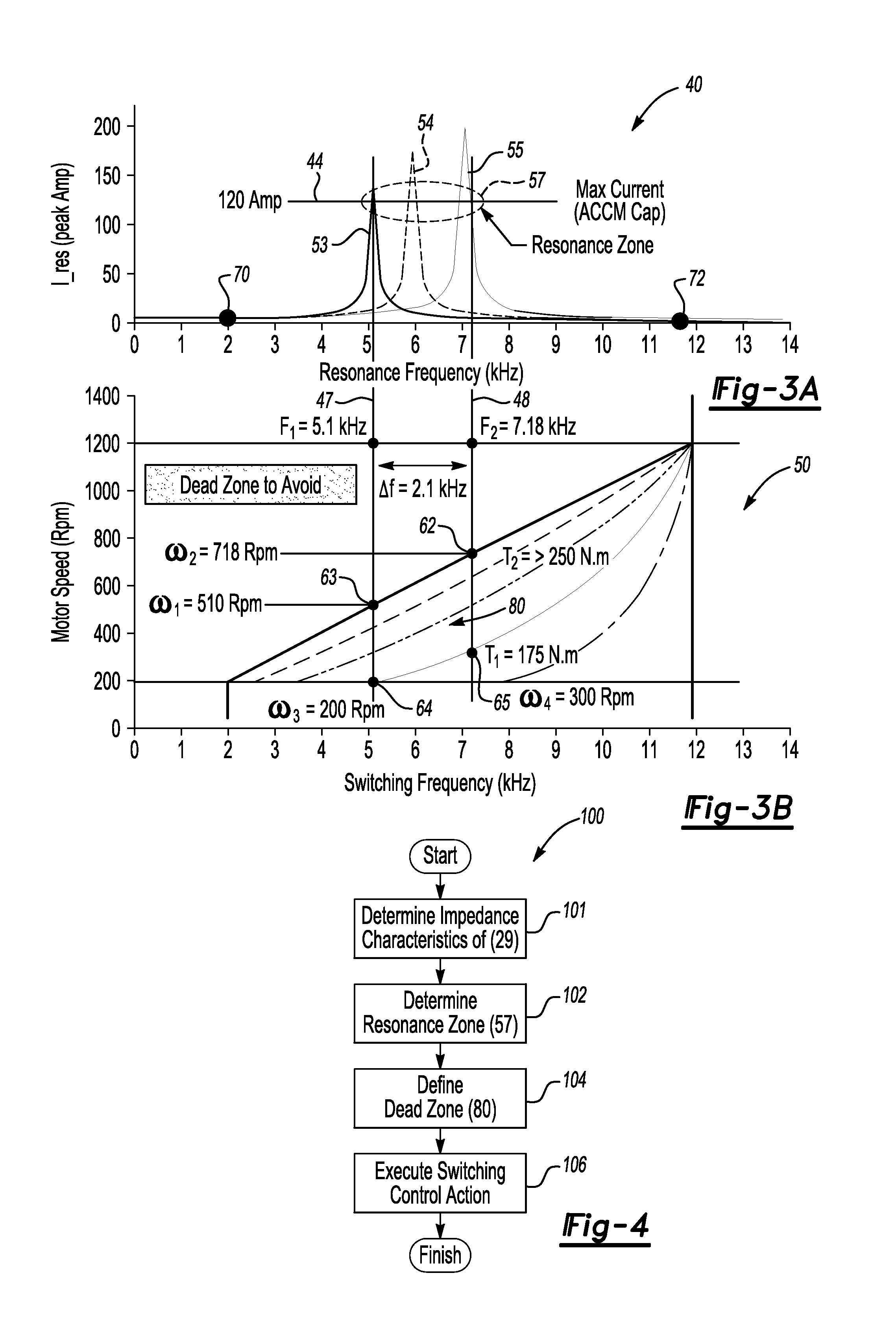
[0008]Such an HV circuit may include a power electronic converter in the form of a traction power inverter module (TPIM). The TPIM may be configured as a pulse-width modulated (PWM) inverter device, where a PWM switching frequency follows a profile that varies between a low value and a high value, e.g., a range of approximately 2 kHz to approximately 12 kHz according to one embodiment. This variation may occur as a function of motor operating speed and torque in order to achieve certain performance objectives, such as but not limited to reduced engine cranking noise, improved inverter efficiency, and lower thermal stress.
[0010]One way to avoid such electrical resonance is to design the ACCM filter components to produce a resonance frequency that is either lower than or higher than the lower range limit of the TPIM, e.g., lower than approximately 2 KHz or higher than approximately 12 KHz in the embodiment noted above. Using that example, to produce a resonance frequency lower than 2 KHz the filter components may be too large to effectively implement in terms of packaging size and cost. Likewise, to produce a resonance frequency higher than 12 kHz in the same embodiment, the filter components may have to be too small to meet ripple requirements, and thus to ensure optimal control stability.
[0011]Accordingly, the method of the present invention, which may be embodied in algorithm form and automatically executed via a controller aboard the vehicle, provides a software-based solution for devising an optimal PWM switching frequency profile. This profile avoids a resonance frequency range between shared electronic power converter devices, e.g., a TPIM and an ACCM.
[0012]In particular, the method avoids electrical resonance in a vehicle having a high-voltage (HV) direct current (DC) bus shared by a first and a second power electronic converter device, e.g., an Air Conditioning Compressor Module (ACCM) and a Traction Power Inverter Module (TPIM), respectively. The method includes determining an impedance characteristic of the shared DC bus, which defines the resonance points thereof. Lower and upper frequency boundaries are selected for the switching frequencies of the second power electronic converter device, such that the second device does not excite the resonance in the DC bus. The method then prevents the switching frequency of the second device from operating within the range (F1, F2) to thereby avoid electrical resonance in the HV DC bus.

Problems solved by technology

Such a resonance may cause a voltage oscillation that may produce an AC current swing potentially affecting the life expectancy of one or more circuit devices.
Acoustic noise may also occur if the electrical resonance matches the natural frequency of a mechanical structure aboard the vehicle.
This PWM switching frequency may generate thermal stresses on the various power switches of the ACCM.

Method used


Image

  • Method and apparatus for avoiding electrical resonance in a vehicle having a shared high-voltage bus
  • Method and apparatus for avoiding electrical resonance in a vehicle having a shared high-voltage bus
  • Method and apparatus for avoiding electrical resonance in a vehicle having a shared high-voltage bus

Examples


Embodiment Construction

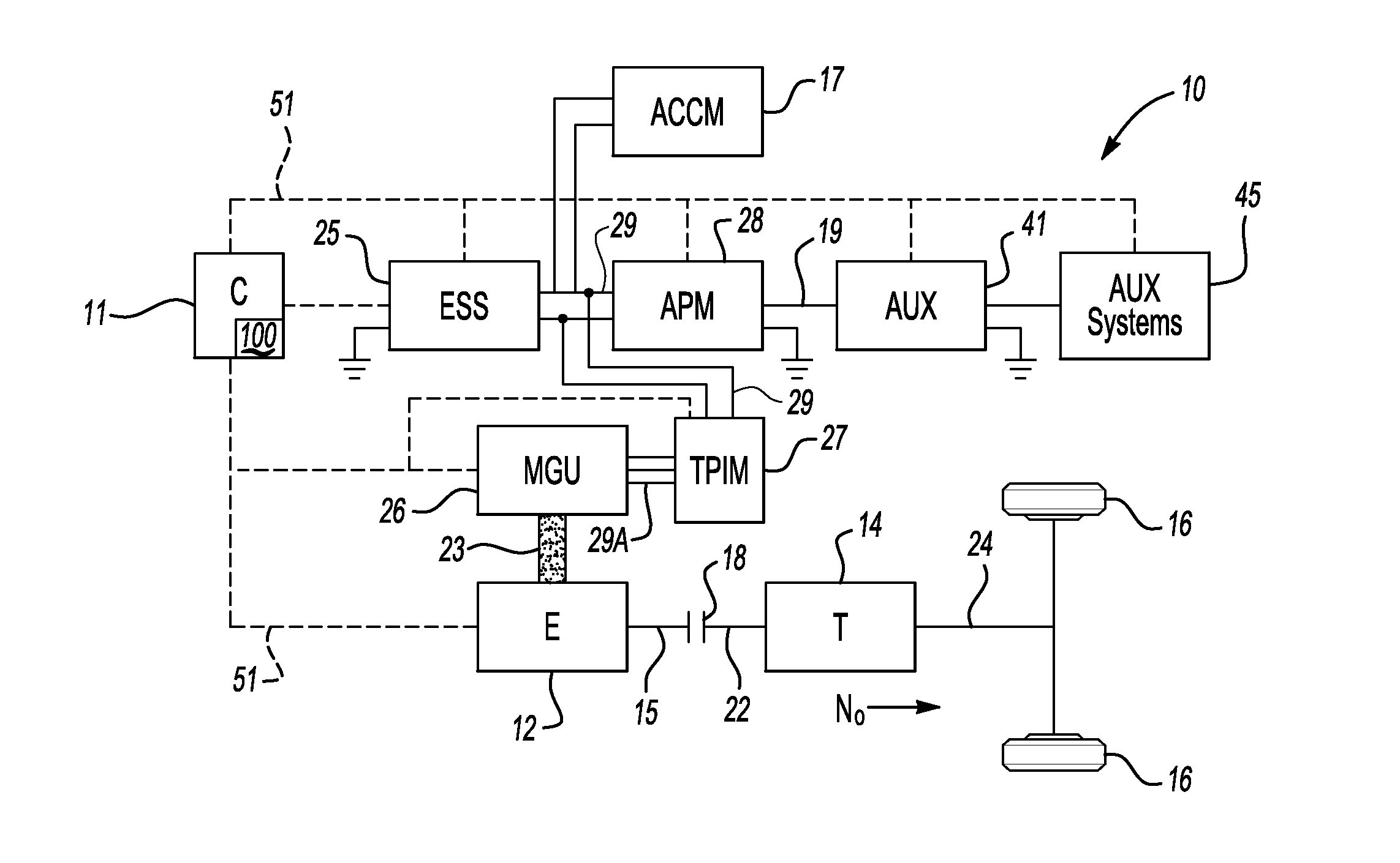
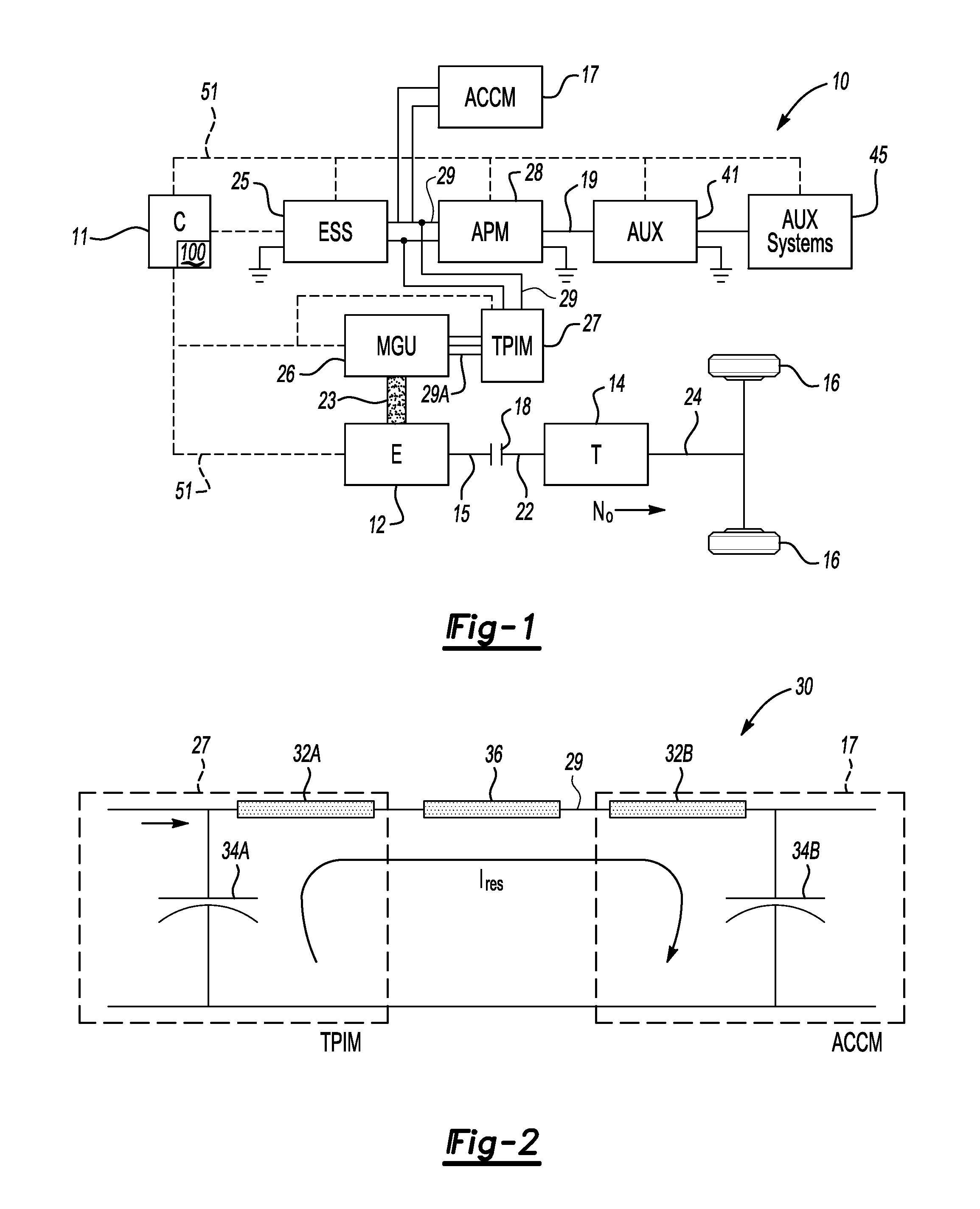
[0020]Referring to the drawings, wherein like reference numbers correspond to like or similar components throughout the several figures, FIG. 1 shows a high-voltage (HV) propelled vehicle 10. The vehicle 10, which may be configured as a hybrid electric vehicle (HEV) in one embodiment as shown, includes a controller (C) 11 having an algorithm 100 adapted for avoiding electrical resonance on a shared HV direct current (DC) bus 29 as explained below.

[0021]The vehicle 10 may include an internal combustion engine (E) 12 having an input member (not shown) and an output member 15 when configured as an HEV as shown. The vehicle 10 includes a transmission (T) 14 having an input member 22 and an output member 24. Output member 15 of the engine 12 may be selectively connected to the input member 22 of the transmission 14 via a torque transfer mechanism 18. The transmission 14 may be configured as an electrically variable transmission (EVT) or any other suitable transmission capable of transmit...


PUM


Abstract

A method for avoiding electrical resonance in a vehicle having a high-voltage (HV) direct current (DC) bus shared by a first and a second power electronic converter device, such as an air conditioning compressor module (ACCM) and a traction power inverter (TPIM), includes determining an impedance characteristic of the bus, defining resonance points for the bus, selecting lower and upper switching frequency boundaries for the TPIM, and preventing the TPIM from operating within a range defined by these boundaries. A vehicle includes the first and second power electronic converter device, e.g., the APPM and the TPIM, the shared HV DC, and a controller having the algorithm set forth above, wherein the controller is adapted for avoiding electrical resonance in the HV DC bus by executing the algorithm.

Description

TECHNICAL FIELD[0001]The present invention relates to power flow control aboard a high-voltage propelled vehicle, and in particular a method and apparatus for avoiding electrical resonance in a vehicle having a high-voltage (HV) bus that is shared by multiple HV power electronic converter devices.BACKGROUND OF THE INVENTION[0002]In certain high-voltage propelled vehicles such as hybrid-electric vehicles (HEV), plug-in hybrid electric vehicles (PHEV), and electric vehicles (EV), a relatively high-voltage (HV) power supply, e.g., a battery or other electrochemical energy storage device, provides a source of at least a portion of the required propulsive power. If so equipped, an engine may be selectively powered off when the vehicle is idling or at a standstill in order to conserve fuel, and / or the vehicle can run entirely on electrical power provided by the HV power supply depending on the vehicle design.[0003]The HV power supply can store energy at a relatively high voltage, typicall...

Claims


Application Information

Patent Timeline
Patent Type & Authority Applications(United States)
IPC IPC(8): B60L1/00
CPCB60K6/48B60L11/14B60L15/20B60L2270/145Y02T10/70Y02T10/6221Y02T10/7077Y02T10/7275H02M1/44B60L50/16Y02T10/62Y02T10/64Y02T10/7072Y02T10/72
Inventor ANWAR, MOHAMMAD N.SCHULZ, STEVEN E.GREEN, STEPHAN N.TARCHINSKI, JAMES E.
Owner GM GLOBAL TECH OPERATIONS LLC
Learn More