
High pressure duckbill valve and insert

a duckbill valve and high-pressure technology, applied in the field of check valves, can solve the problems of no inventor known, handling more than 20 psi back pressure, and large particulates, and achieve the effect of good suppor

Active Publication Date: 2011-05-12
XYLEM IP HLDG
View PDF43 Cites 38 Cited by
  • Summary
  • Abstract
  • Description
  • Claims
  • Application Information

AI Technical Summary

Benefits of technology

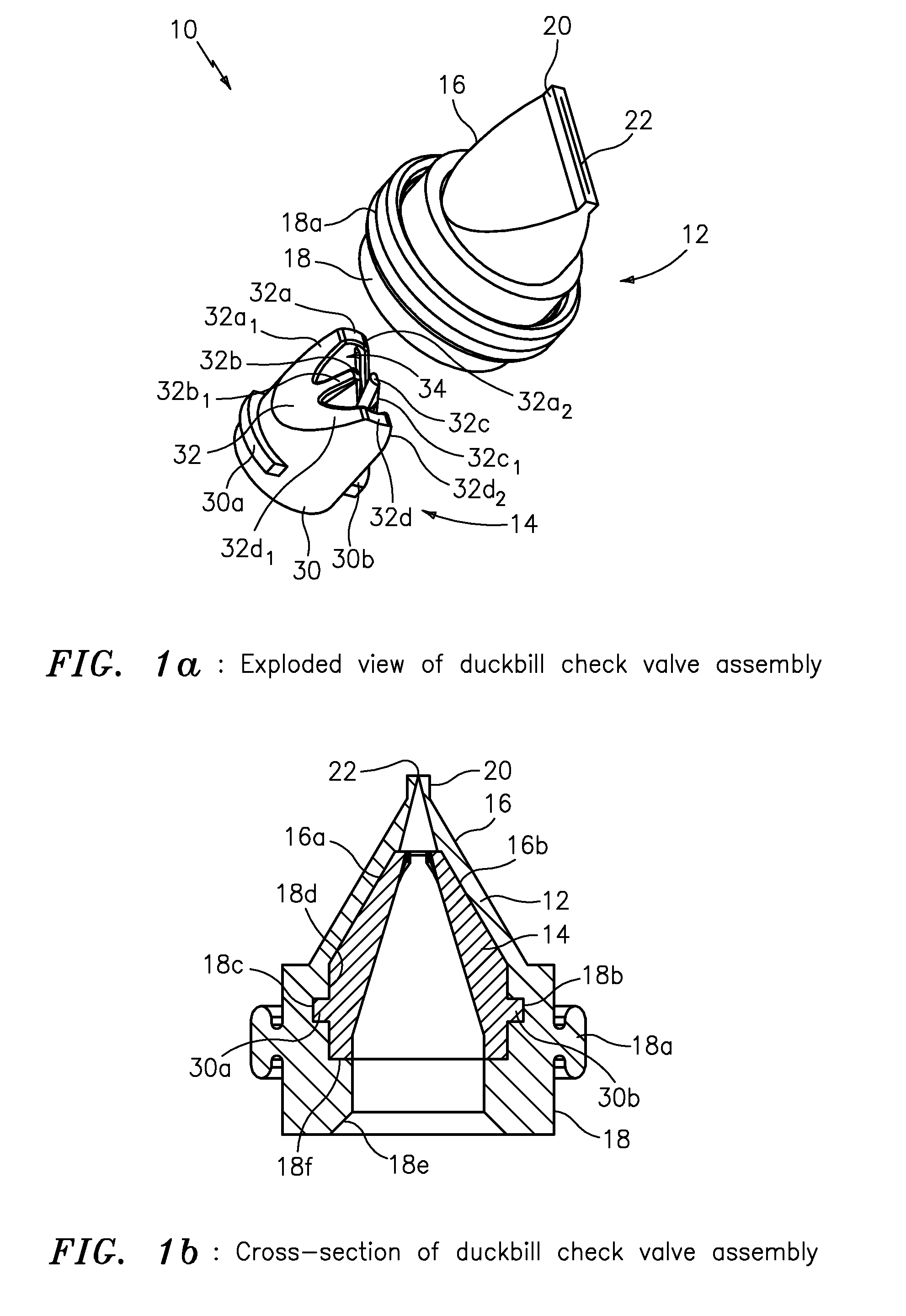
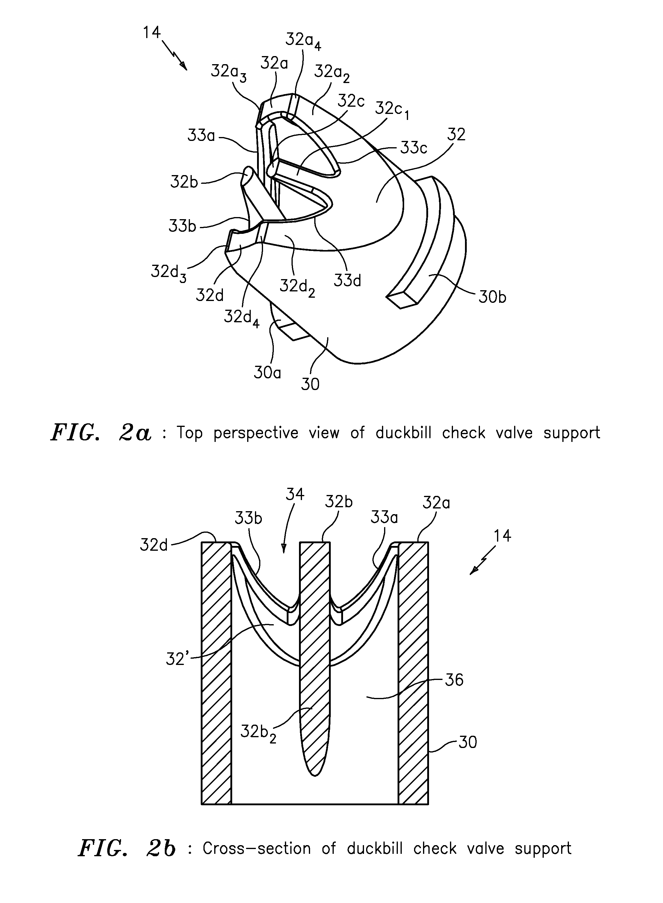
[0025]In operation, fluid flows through the duckbill check valve assembly and a duckbill portion of the duckbill check valve seat opens to pass the fluid and particulates. When the dispense valve or similar device is closed, the duckbill portion closes and as pressure increases the rigid insert supports the walls of the duckbill check valve seat, so as not to collapse, causing the duckbill check valve assembly to at least partially fail. The unique design of the rigid insert according to the present invention allows for the duckbill portion of the duckbill check valve seat to provide a larger opening for the passing of particulates, and to provide support for higher back pressures (up to 80 PSI) than typical known duckbill check valve designs. The rigid insert also has two (2) raised radially extending locating tabs, wings or protrusions to help locate and maintain the location of the rigid insert within the check valve seat to align the insert in relation to the seat when arranged therein, and to prevent the insert from being pushed out by the back pressure.
[0028]According to some embodiments of the present invention, the duckbill check valve support may include two locating tabs or wings, and the base portion of the duckbill check valve seat may include two locating recesses arranged in its internal walls and configured to receive the two locating tabs or wings in order to axially align the duckbill check valve seat in relation to the duckbill check valve support in a proper orientation and at a proper depth, as well as to prevent the duckbill check valve support from being pushed out of the duckbill check valve seat due to back pressure.
[0031]In effect, according to the present invention the rigid insert can be used to strengthen a duckbill check valve seat against back pressure, far in excess of 20 PSI. The insert has a new and unique concave shape with a “W” design, which keeps good support for the main check valve but also allows large particulates to pass through the center.

Problems solved by technology

There are many duckbill valves available on the market but none known to the inventors so far that can handle higher than 20 PSI back pressure and large particulates at the same time.
None of the known prior art developed in the search included a plastic insert that can be used to strengthen a duckbill valve against back pressure, especially where the insert has a special concave shape with a “W” design, which keeps good support for the main check valve but also allows large particulates to pass through the center.

Method used


Image

  • High pressure duckbill valve and insert
  • High pressure duckbill valve and insert
  • High pressure duckbill valve and insert

Examples


Embodiment Construction

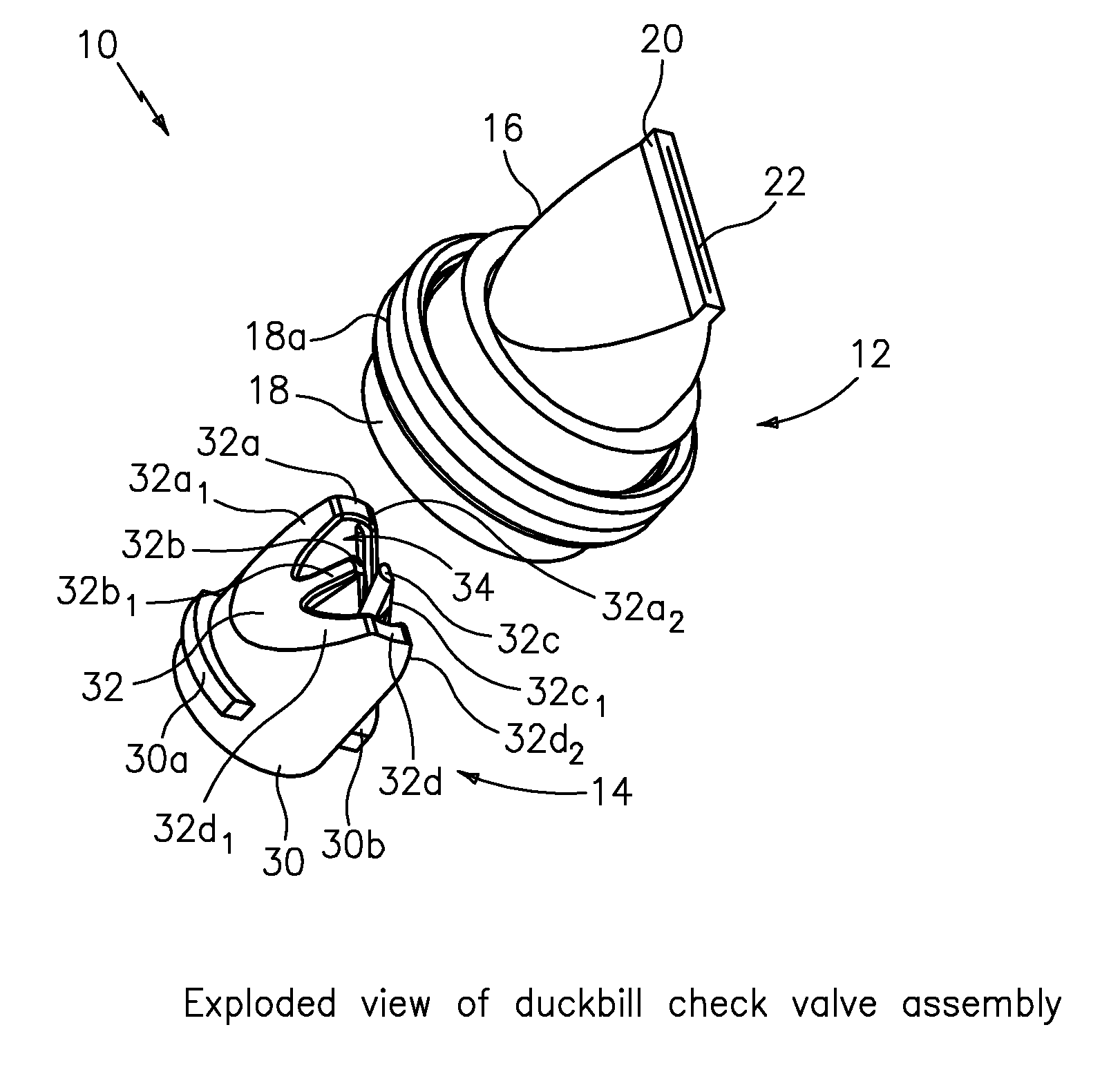
[0056]The duckbill check valve assembly 10FIGS. 1a and 1b show a duckbill check valve assembly generally indicated as 10 according to some embodiments of the present invention, which includes a duckbill valve in the form of a duckbill check valve seat 12 (see FIGS. 3a through 3j) and an insert for arranging inside in the form of a duckbill check valve support 14 (see FIGS. 2a through 2j).

The Duckbill Check Valve Seat 12

[0057]The following description of duckbill check valve seat 12 is provided by way of example. The scope of the invention is intended to include deviations from that shown and description so as to still be within the spirit of the invention.

[0058]As shown in FIGS. 1a and 1b, the duckbill check valve seat 12 is made of pliable material, shaped like the beak of a duck, and configured with a duckbill portion 16 and a base portion 18. The duckbill portion 16 is configured with a flattened end 20 having a slit 22 to flex open so as to allow and provide fluid and particulat...


PUM


Abstract

The present invention provides apparatus featuring a check valve featuring a duckbill valve configured to provide fluid and particulate; and an insert having a base portion configured to seat the insert inside the duckbill valve, and a W-shaped portion configured with an opening to pass the fluid and particulate through the duckbill valve and also configured to provide support for walls of the duckbill valve in response to back pressure caused by the fluid and particulate.

Description

CROSS-REFERENCE TO RELATED APPLICATIONS[0001]This application claims benefit to provisional patent application Ser. No. 61 / 161,858, filed 20 Mar. 2009, which is hereby incorporated by reference in its entirety.BACKGROUND OF THE INVENTION[0002]1. Field of the Invention[0003]The present invention relates to a check valve for providing fluid and particulate; and more particularly relates to an insert for a check valve having a duckbill valve for providing fluid and particulate.[0004]2. Brief Description of Related Art[0005]In general, a duckbill valve is known as a valve, manufactured from pliable material, e.g., rubber or synthetic elastomer, and shaped like the beak of a duck. It is commonly used in medical applications to prevent contamination due to backflow. Typically, one end of the duckbill valve is configured to stretch over the outlet of a supply line, conforming itself to the shape of the line, usually round. The other end of the duckbill valve has walls that converge so as t...

Claims


Application Information

Patent Timeline
Patent Type & Authority Applications(United States)
IPC IPC(8): F16K15/00
CPCF16K15/147Y10T137/7837Y10T137/7882Y10T137/7886
Inventor WRIGHT, PETERROMERO, ROBERT J.PHILLIPS, DAVID L.
Owner XYLEM IP HLDG
Learn More