
Engine With Variable Compression Ratio

a compression ratio and variable technology, applied in the field of automotive engines, can solve the problems of unstable engine operation, reduced engine thermal efficiency, and inability to adapt to the different combustion characteristics of different fuels, and achieve the effect of optimizing fuel economy and dynamic performance of the engin

Inactive Publication Date: 2011-05-12
XIONG ZHIJIANG +1
View PDF3 Cites 11 Cited by
  • Summary
  • Abstract
  • Description
  • Claims
  • Application Information

AI Technical Summary

Benefits of technology

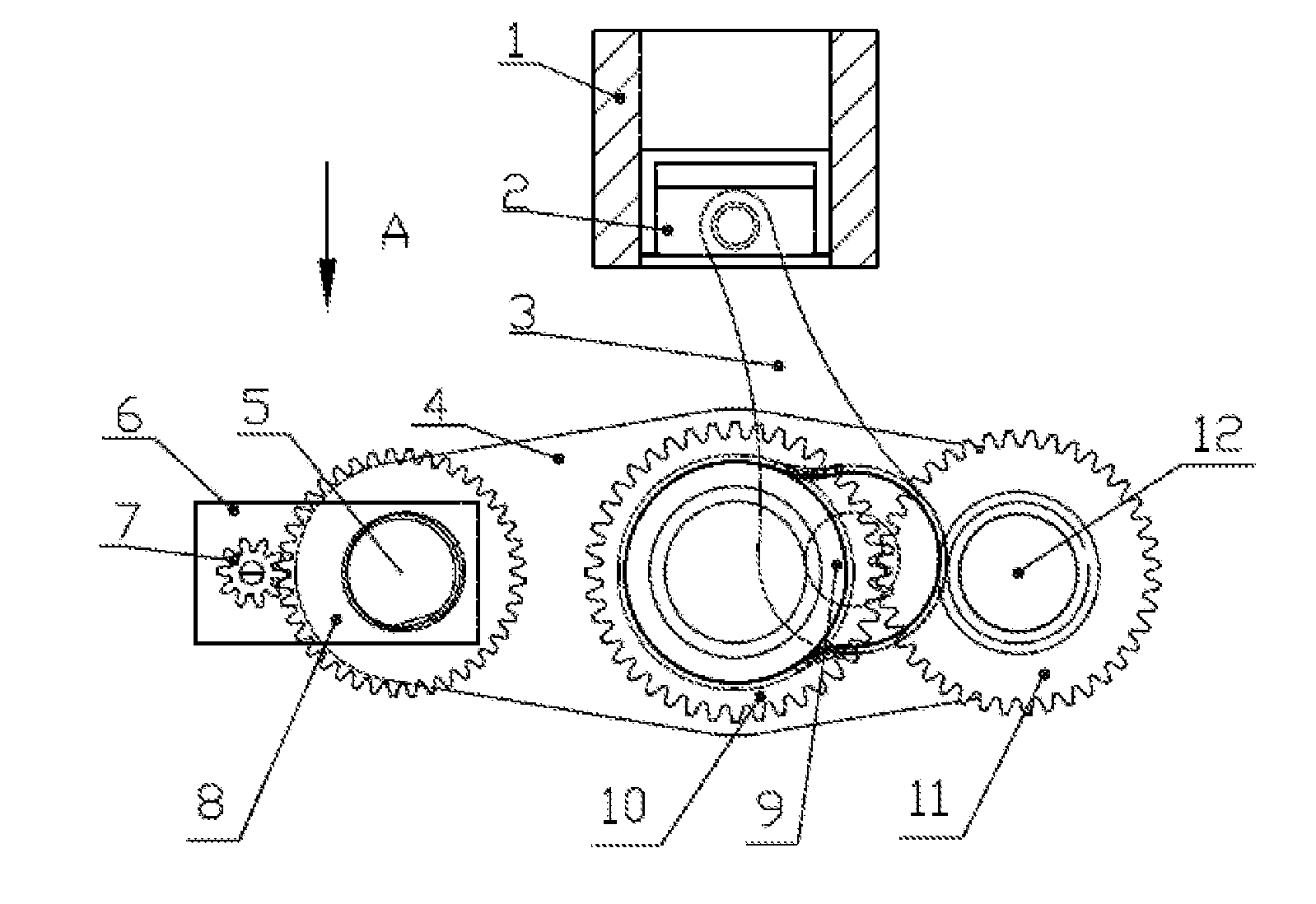
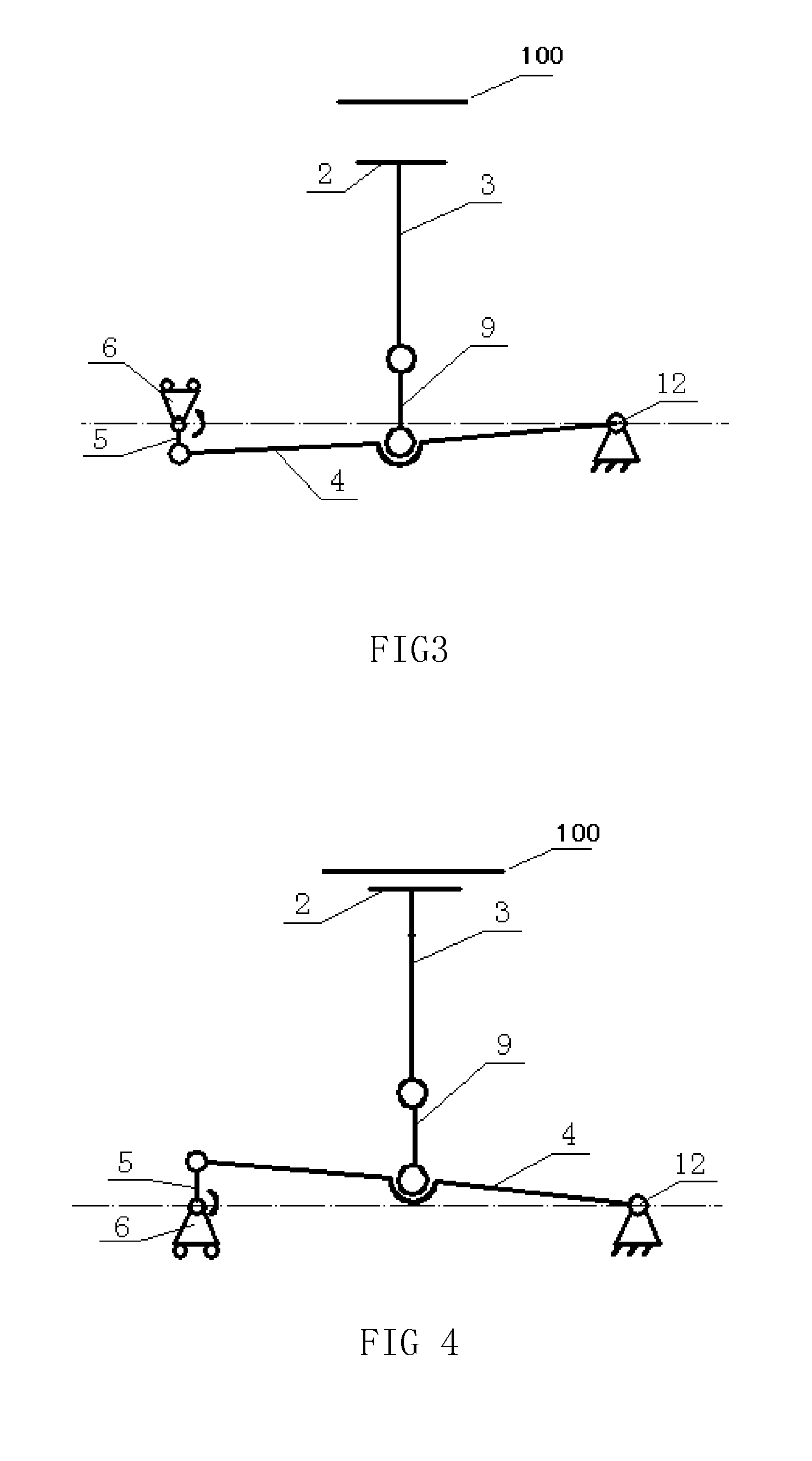
[0006]The engine with variable compression ratio of the present invention is divided into two parts, namely, an upper part comprising a cylinder cover and a lower part comprising a cylinder body and a crankshaft box. The upper part remains unchangeable, in the lower part, based on the principle of lever; a supporting arm is used to adjust the position of the crankshaft center. Specifically, under the control of the controlling mechanism, the supporting arm rotates around the position where the supporting arm is hinged onto the cylinder body so as to realize a small displacement of the crankshaft center position relative to the cylinder body, and as a result, the position of the top dead point of the engine is changed, and the compression ratio of engine also is changed accordingly. Thanks to the controlling mechanism, the compression ratio of such an engine with variable compression ratio is controllable, and it is feasible to realize the compression ratios that are best adapted to the various operating conditions.
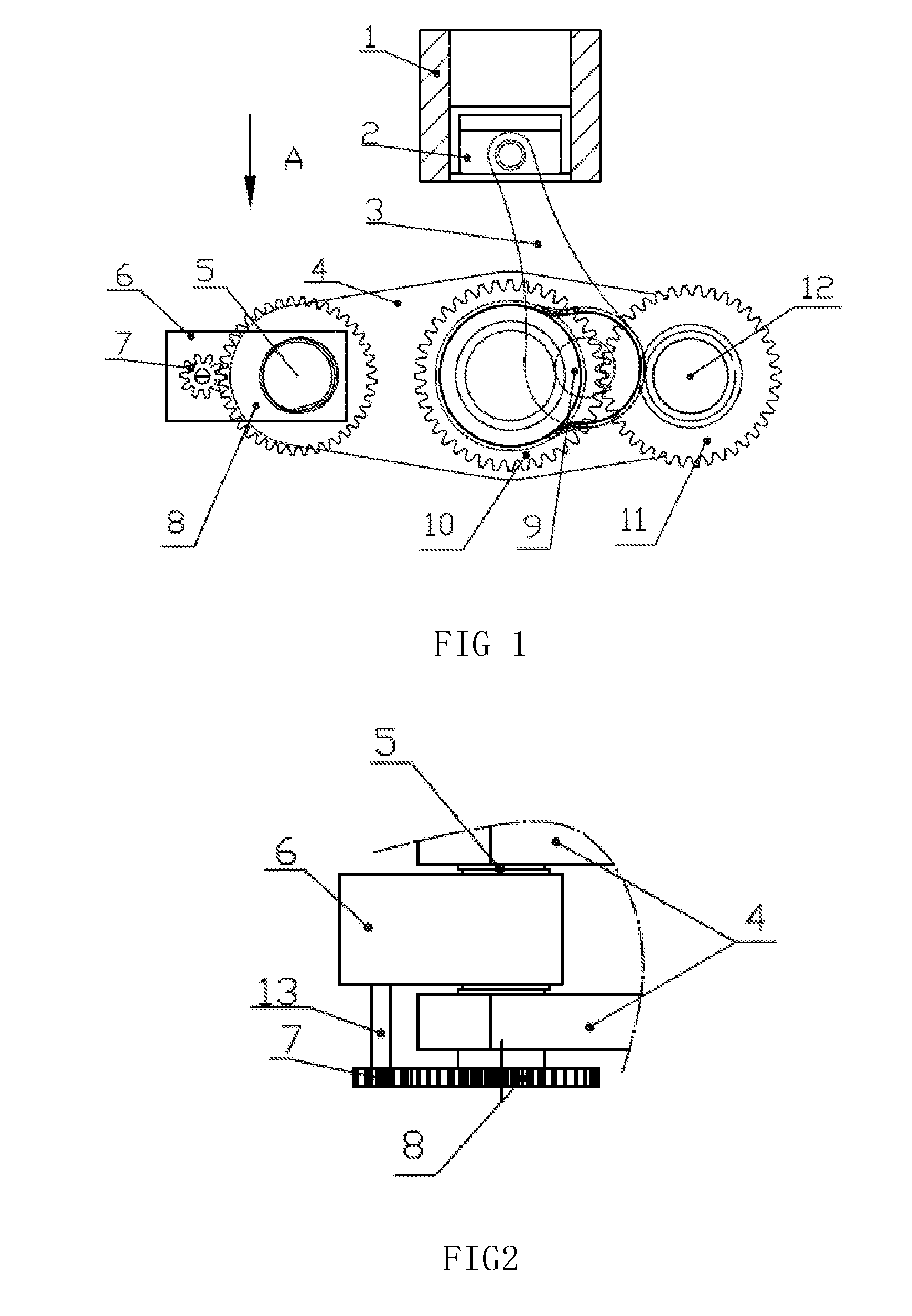
[0008]Designed based on the principle of eccentric action, the controlling mechanism uses the control motor to drive the rotation of eccentric shaft. As a result, the control end of the supporting arm can make up and down movement so as to realize the slight displacement of the crankshaft center position relative to the cylinder body and the change in the compression ratio of engine. For engines adopting such technical solution, when it is necessary, the compression ratio may be varied through manipulating the control motor to drive the rotation of eccentric shaft so as to change the distance between the crankshaft center and the cylinder body. As a result, based on such adapted compression ratios corresponding to different operating conditions, the optimal fuel economy and dynamic performance of the engine may be achieved.

Problems solved by technology

In addition, the current flexible-fuel engines are unable to adapt to the different combustion characteristics of different fuels due to the constant compression ratio of the engines thereof.
For examples, when an engine is refilled with a different fuel, the thermal efficiency of the engine is reduced, and abnormal combustion phenomena, including knocking, can easily occur; switching to a different fuel in the process of driving may also easily results in unstable operation of the engine and other abnormal phenomenon.
However, the change in the compression ratio of internal combustion engine results from the change in the length of connecting rod, which is caused by deformation of the spring under stress exerted thereupon, and which is completed during the multiple strokes of the internal combustion engine, such a change in the compression ratio is uncontrollable, therefore the patent documentation with application number of 88101975.5 is unable to provide the flexible-fuel engine with the compression rations that are adaptable to different fuels.

Method used


Image

  • Engine With Variable Compression Ratio
  • Engine With Variable Compression Ratio
  • Engine With Variable Compression Ratio

Examples


Embodiment Construction

[0014]FIG. 1 is an overall structural diagram of the present invention; FIG. 2 is an A-direction partial view in FIG. 1. As shown in FIG. 1 and FIG. 2, the present invention provides an engine with variable compression comprising a cylinder cover, a cylinder body 1, a crankshaft box and a power output shaft 12. The cylinder cover is fixed on the cylinder body 1, and the crankshaft box and the cylinder body 1 are formed into an integral body. In the cylinder body 1, a piston 2 is connected with a crankshaft 9 via a connecting rod 3, the power output shaft 12 is mounted on the crankshaft box. A power output gear 11 and a input gear 10 engaging each other are mounted on the power output shaft 12 and the crankshaft journal 9 respectively. Further provided in the crankshaft box is a supporting arm 4, onto which the crankshaft 9 is mounted, and one end of which is hinged on the cylinder body 1 with the power output shaft 12 used as the hinging axis. The other end of the supporting arm is ...


PUM


Abstract

The present invention provides an engine with variable compression ration comprising a cylinder cover, a cylinder body, a power output shaft and a crankshaft box, the cylinder cover is fixed on the cylinder body, the crankshaft box is formed with the cylinder body integrally; In the cylinder body, an piston is connected with a crankshaft via a connecting rod; the power output shaft is mounted on the crankshaft box; a power output gear is placed on the power output shaft, an input gear is placed on a crank journal of the crankshaft, the power output gear engages with the input gear; A supporting arm is placed in the crankshaft box, the crankshaft is hinged on the supporting arm; one end of the supporting arm is hinged on the crankshaft box, and the hinging shaft is the power output shaft; the other end of the supporting arm is a control end, the control end is connected with a rotation control mechanism, which can make the supporting arm rotate around the power output shaft. Since the rotation control mechanism is used to make displacement control over the control end of the supporting arm, the compression ratio of engine matches the engine behavior, so that the efficiency is improved while the emission is reduced.

Description

FIELD OF THE INVENTION[0001]The present invention relates to an automotive engine, in particular to an engine with variable and controllable compression ratio, which pertains to the technical field of machinery manufacture.DESCRIPTION OF THE PRIOR ART[0002]At present, most of engines have immutable compression ratios. However, in order to achieve different purposes, such as, reducing fuel consumption, improving engine performance and reducing emission under different operating conditions, it is necessary to flexibly change the compression ratios of engines according to different operating conditions. In addition, the current flexible-fuel engines are unable to adapt to the different combustion characteristics of different fuels due to the constant compression ratio of the engines thereof. For examples, when an engine is refilled with a different fuel, the thermal efficiency of the engine is reduced, and abnormal combustion phenomena, including knocking, can easily occur; switching t...

Claims


Application Information

Patent Timeline
Patent Type & Authority Applications(United States)
IPC IPC(8): F02B75/04F02D15/04
CPCF02B75/047Y02T10/12F02D15/02
Inventor XIONG, ZHIJIANGLU, NENGCAI
Owner XIONG ZHIJIANG
Learn More