Holding structure for a touch panel

a technology of holding structure and touch panel, which is applied in the direction of instruments, computing, electric digital data processing, etc., can solve the problems of dust or drips entering from the outside, affecting the operation of the touch panel, and unable to feel or be sure whether the contact is closed or not, so as to achieve good force feedback effect, reduce the cost of the holding structure, and improve the effect of force feedback function

Inactive Publication Date: 2011-05-05
SMK CORP
View PDF4 Cites 37 Cited by
  • Summary
  • Abstract
  • Description
  • Claims
  • Application Information

AI Technical Summary

Benefits of technology

[0014]The present invention is achieved in consideration of the problems of the related arts mentioned above. The purpose of this invention is to provide a holding structure for a touch panel with a simple composition, of high dust-proof feature and drip-proof feature, and with effective transmission characteristics of the vibration of the touch panel to the operator.
[0019]The dust-proof feature and the drip-proof feature at the interspace between the touch panel and the display panel can be improved by the supporting member and the supporting frame being integrated with each other. More secured support, dust-proof feature and drip-proof feature can be achieved, especially, by making the supporting frame serve as the supporting member, and good force feedback effects can also be achieved. Furthermore, better dust-proof feature and drip-proof feature can be achieved by bonding with adhesives.
[0020]By making the flexible substrate of the touch panel serve as the resin sheet holding the touch panel, the cost of the holding structure can be reduced, and a good force feedback function, dust-proof feature and drip-proof feature can be achieved. Or also by making a protection sheet covering the touch panel front surface serve as the resin sheet holding the touch panel, a good force feedback function, dust-proof feature and drip-proof feature can be achieved. In this way, the holding structure of an excellent design or high durability can be achieved.

Problems solved by technology

Even though the ITO films on the upper and the lower panels get in contact with each other when an operator presses the surface of the touch panel, the operator can neither feel nor be sure whether the contact is closed or not.
In the case of the touch panel device equipped with the force feedback function shown in FIG. 6 of the related arts mentioned above, a bit of interspace 6b is disposed between the peripheral edge of the opening 6a of the casing and the front surface of the touch panel 4 in order to vibrate the touch panel, and there remains a problem that dust or drips are liable to enter from the outside and to give a bad influence on the liquid crystal panel 2 or other electronic elements.
On the other hand, as it is disclosed in Japanese Patent Application Publication No. 2002-2229672 and No. 2000-276254, the dust-proof feature and the drip-proof feature become improved by making close contact and fixing the front surface of the touch panel with the peripheral edge of the opening of the casing, however, there remains a problem that the vibration of the touch panel is suppressed and the force feedback function comes to be deteriorated.

Method used


Image

  • Holding structure for a touch panel
  • Holding structure for a touch panel
  • Holding structure for a touch panel

Examples


first embodiment

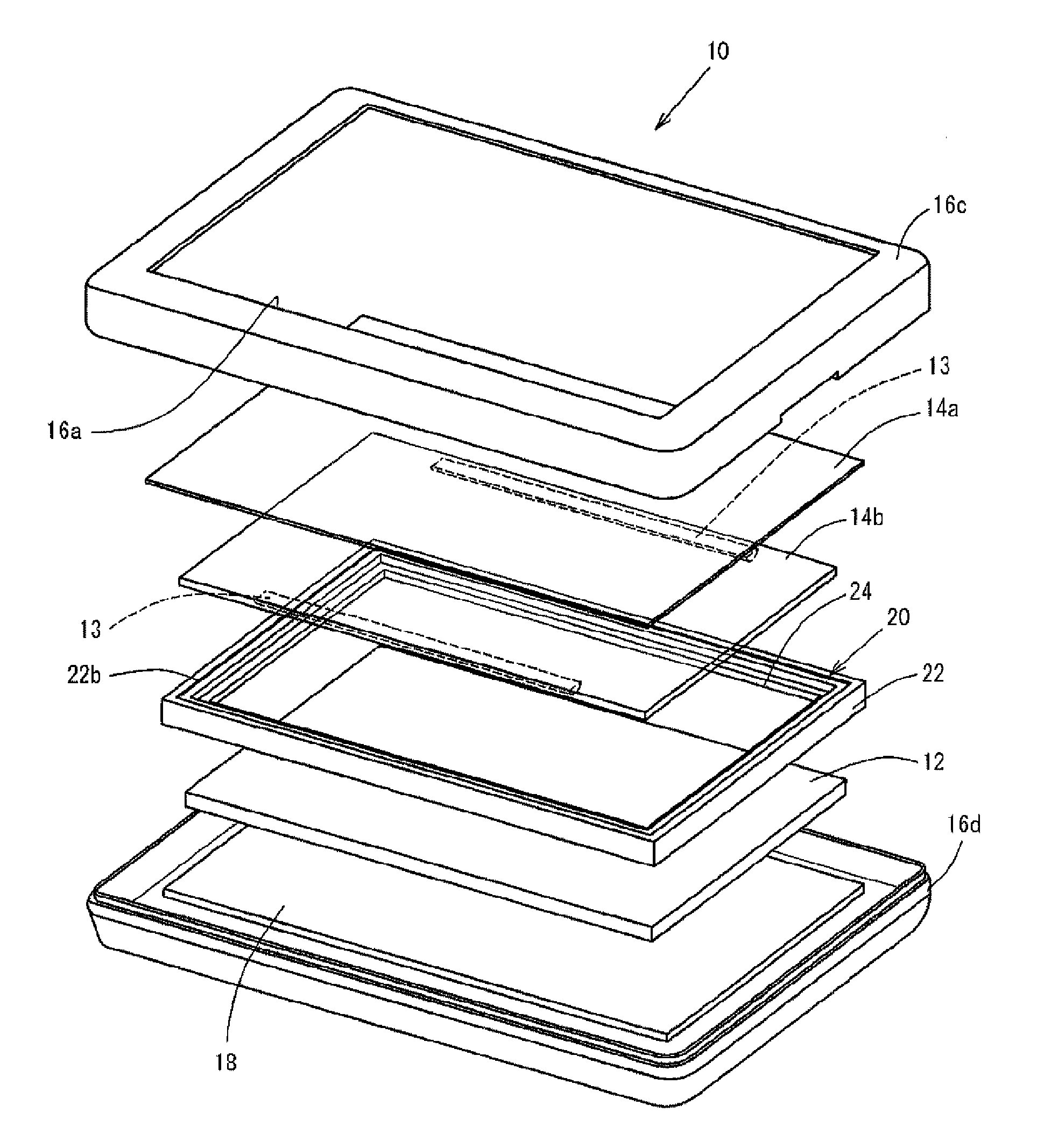
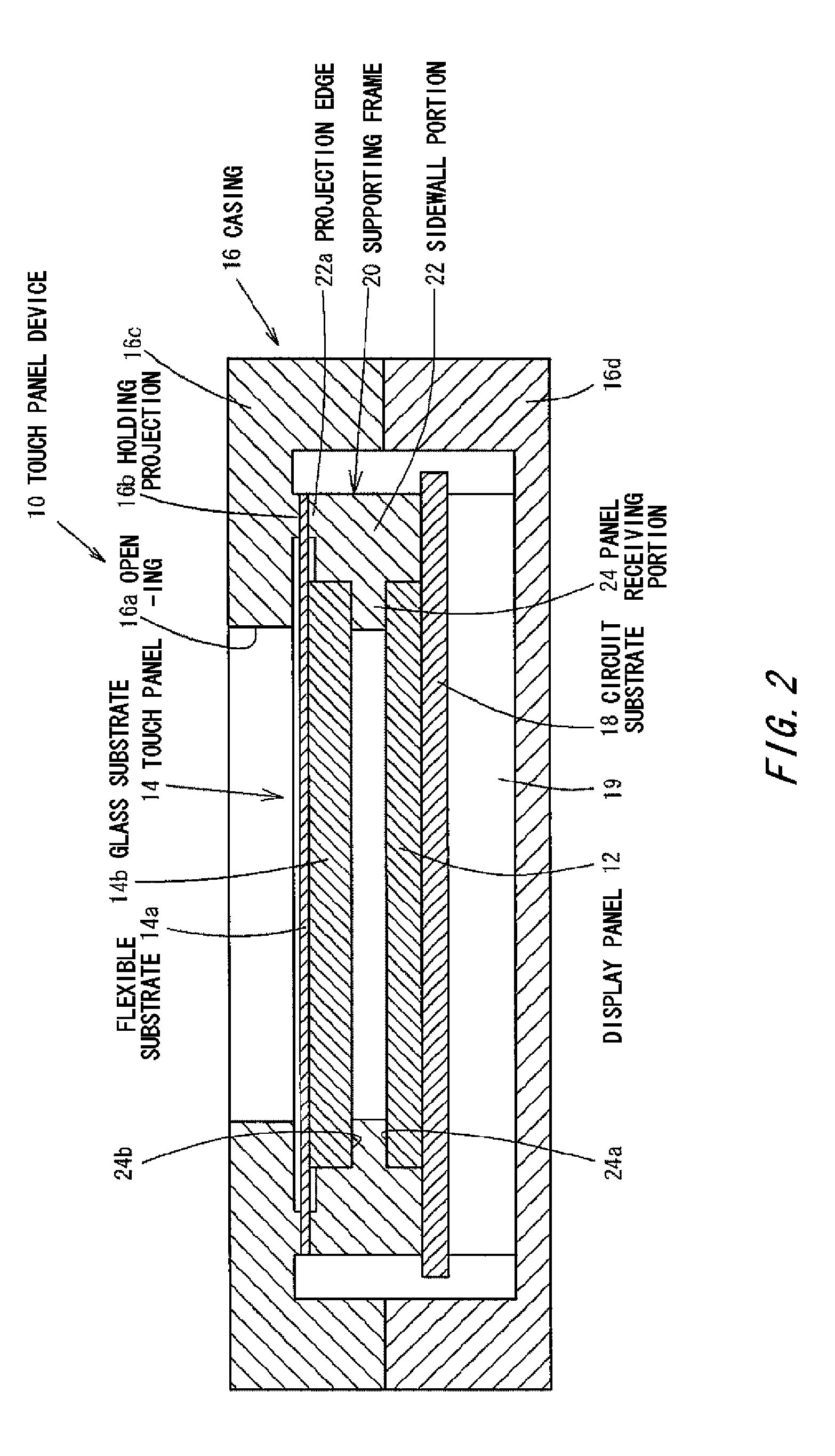
[0027]Hereinafter, the embodiments related to the present invention are to be explained based upon Figures. FIG. 1 and FIG. 2 show the first embodiment related to the present invention. The touch panel device 10 in the embodiment illustrates an embodiment used in a portable information terminal device. In addition, a touch panel is also used as an input device serving as various display panels in a computer display, a vehicle navigation device, an automated teller machine, a ticket vending machine or the like. The touch panel device 10 is provided with such a display panel 12 as a liquid crystal display panel or an electroluminescence display panel and a touch panel 14 for allowing input operation, and has a casing 16 molded by resin or the like accommodating a display panel 12 and a touch panel 14. The casing 16 takes almost a box-shape being divided into two in a transverse direction, and an opening 16a is formed. The casing 16 has a front surface portion 16c where an opening 16a ...

second embodiment

[0036]Hereinafter, a holding structure for a touch panel related to the present invention is to be explained based upon FIG. 3 and FIG. 4. Here, the same symbols are allocated to the same or similar members appeared in the embodiment mentioned above and the explanation is omitted. In the touch panel 14 in accordance with the embodiment, the flexible substrate 14a and the glass substrate 14b, both of which constitute the touch panel 14, are formed in the same size. A flexible protective sheet 17 made of PET resin or the like is applied to the front surface of the flexible substrate 14a. The protective sheet 17 is formed to have a size entirely larger than the touch panel 14 and the resin sheet of the protective sheet 17 is disposed extending at an entire periphery of the touch panel 14.

[0037]In the embodiment, the entire peripheral edge of the protective sheet 17 applied to the touch panel 14 is tightly held between the holding projection 16b formed at a peripheral edge of the rear s...


PUM


Abstract

A holding structure for a touch panel has a display panel, a touch panel for allowing an input operation, a supporting frame for holding the display panel at an entire peripheral edge a piezoelectric device for applying vibration to the touch panel in accordance with the operation of the touch panel, a casing for holding the display panel and the touch panel via the supporting frame, and a flexible resin sheet integrally provided to the front surface side of the touch panel. The flexible substrate is formed to have a size entirely larger than a glass substrate on a rear surface side of the touch panel. The peripheral edge of the flexible substrate is held by a rear surface of a peripheral edge of the opening of the casing and a supporting member fixed to the casing.

Description

CROSS REFERENCE TO RELATED APPLICATION[0001]The contents of the following patent applications are incorporated herein by reference,[0002]NO. 2009-252059 filed on Nov. 2, 2009, and[0003]NO. 2009-259031 filed on Nov. 12, 2009.BACKGROUND[0004]1. Technical Field[0005]This invention relates to a holding structure for a touch panel, which is provided at a display or an operation unit of a variety of electronic devices and being used as an input device.[0006]2. Description of the Related Art[0007]Conventionally, electronic devices having touch panel function as input means at the display surface have been widely used. One of the structures of the touch panels was a resistance-sensitive type. In the touch panel, a transparent ITO (indium oxide) film is formed on the surface of the touch panel glass in a predetermined pattern. Electrodes are connected to the end portion of the ITO film and the peripheries are coated by over-coating. And dot spacers are provided between the upper layer flexib...

Claims


Application Information

Patent Timeline
Patent Type & Authority Applications(United States)
IPC IPC(8): G06F3/041G06F3/0354
CPCG06F1/1626G06F1/1643G06F3/041G06F3/03547G06F3/016
Inventor IWAWAKI, SHINYAIMAI, KAZUOMIZUKI, TAKAYUKI
Owner SMK CORP
Why Eureka
Try Eureka