
Block lock for a round link chain

a technology of block lock and round link chain, which is applied in the direction of driving chains, chain elements, shackles, etc., can solve the problem of significant limitation of the space in which the chain links can maneuver in the situation of a slack chain, and achieve the effect of reducing the risk of slack chain damag

Active Publication Date: 2011-05-05
THIELE GMBH & CO KG
View PDF7 Cites 3 Cited by
  • Summary
  • Abstract
  • Description
  • Claims
  • Application Information

AI Technical Summary

Benefits of technology

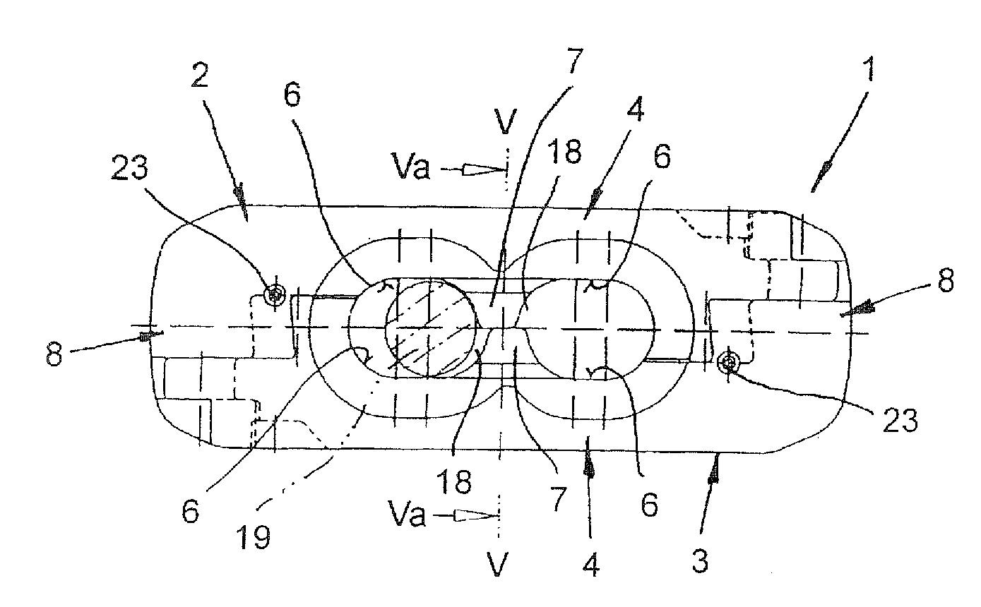
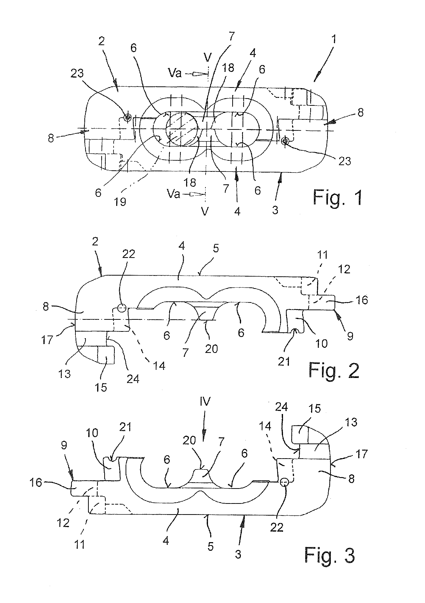
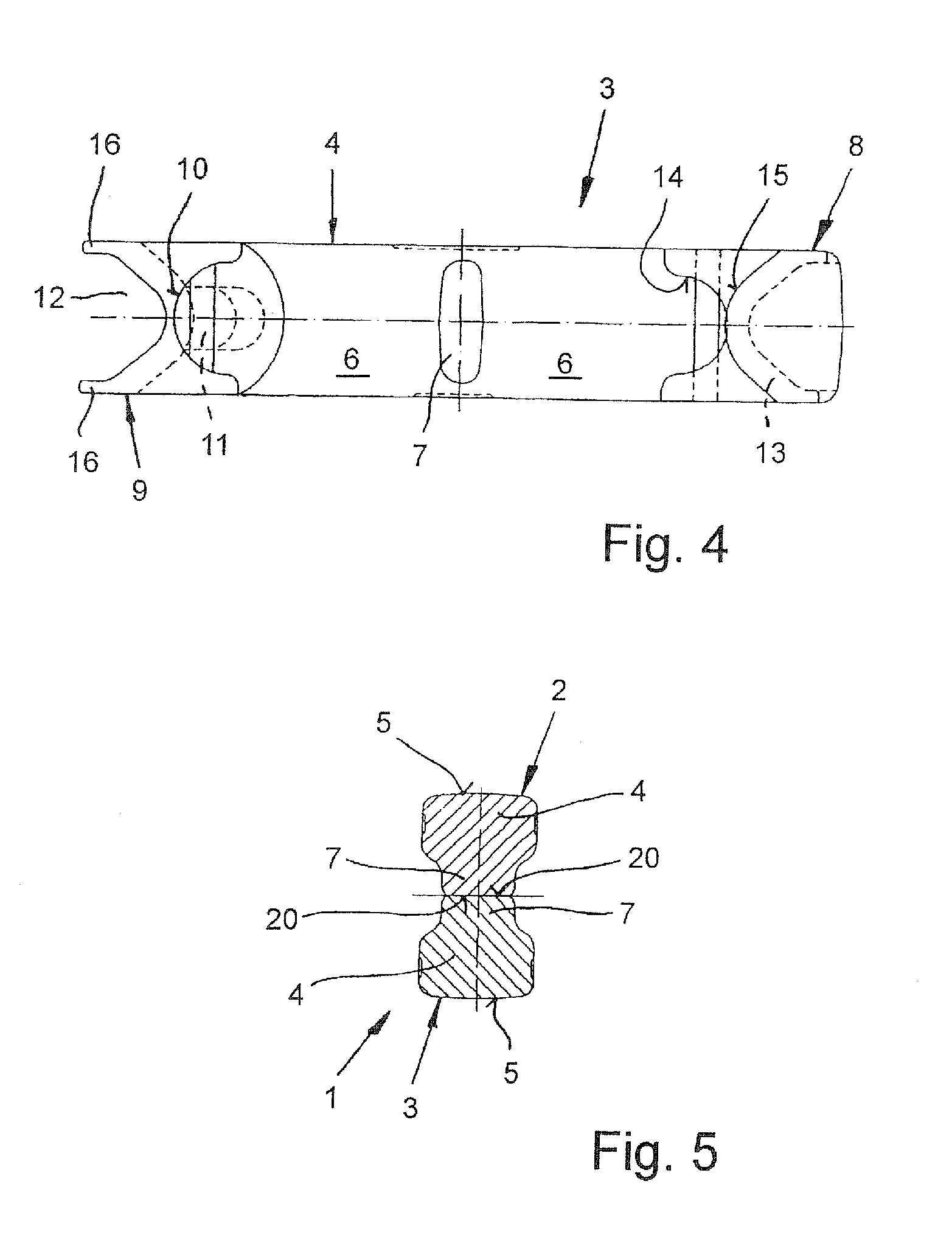
[0010]Another advantage of the free space is that the inserted chain link only contacts that particular center rib where contact with the chain link supports the closing motion of the lock halves and simultaneously contact with the other center rib is prevented, which in case of contact would support the opening motion of the lock halves.
[0013]The center ribs preferably abut each other with their end faces. This prevents the block lock from being constricted at the center under tension.

Problems solved by technology

The room for the chain links to maneuver in the situation of a slack chain is now significantly limited.

Method used


Image

  • Block lock for a round link chain
  • Block lock for a round link chain
  • Block lock for a round link chain

Examples


Embodiment Construction

[0021]Throughout all the figures, same or corresponding elements may generally be indicated by same reference numerals. These depicted embodiments are to be understood as illustrative of the invention and not as limiting in any way. It should also be understood that the figures are not necessarily to scale and that the embodiments are sometimes illustrated by graphic symbols, phantom lines, diagrammatic representations and fragmentary views. In certain instances, details which are not necessary for an understanding of the present invention or which render other details difficult to perceive may have been omitted.

[0022]Turning now to the drawing, and in particular to FIG. 1, there is shown a block lock 1 which includes two identical lock halves 2, 3 having an approximately L-shaped configuration. Each of the lock halves 2, 3 has a longitudinal leg 4 with a center rib 7 which faces away from its continuous back portion 5 and separates bearing shells 6 for chain end links of the round ...


PUM


Abstract

The block lock for round link chains includes two approximately L-shaped lock halves connected with each other by pins. Each lock half has a longitudinal leg with a center rib, which faces away from its continuous back portion and separates bearing shells for chain links, and a cross leg arranged on one end of the longitudinal leg. Projections and receiving pockets are provided on the front ends of the longitudinal legs facing away from the cross legs, and receiving pockets and projections matching the projections and receiving pockets on the longitudinal legs are provided on the sides of the cross legs facing the center ribs. The center ribs are mutually offset in the longitudinal direction of the identically constructed lock halves.

Description

CROSS-REFERENCES TO RELATED APPLICATIONS[0001]This application claims the priority of German Patent Application, Serial No. 20 2009 014 963.3, filed Nov. 3, 2009, pursuant to 35 U.S.C. 119(a)-(d), the content of which is incorporated herein by reference in its entirety as if fully set forth herein.[0002]This application claims the benefit of prior filed U.S. provisional Application No. 61 / 257,613, filed Nov. 3, 2009, pursuant to 35 U.S.C. 119(e), the content of which is incorporated herein by reference in its entirety as if fully set forth herein.BACKGROUND OF THE INVENTION[0003]The present invention relates to a block lock for a round link chain.[0004]The following discussion of related art is provided to assist the reader in understanding the advantages of the invention, and is not to be construed as an admission that this related art is prior art to this invention.[0005]Some conventional block locks for chains include two approximately L-shaped lock halves connected by pins. Each...

Claims


Application Information

Patent Timeline
Patent Type & Authority Applications(United States)
IPC IPC(8): F16G15/02
CPCF16G15/04
Inventor MULLE, WILHELM
Owner THIELE GMBH & CO KG
Learn More