
Method for repairing a gas turbine component

a gas turbine and component technology, applied in the field of gas turbine technology, can solve the problems of cost, loss of mechanical stability and change, limited quality of repair of damaged gas turbine components, etc., and achieve the effects of reducing cost, improving flexibility and productivity, and high quality

Inactive Publication Date: 2011-05-05
ALSTOM TECH LTD
View PDF40 Cites 53 Cited by
  • Summary
  • Abstract
  • Description
  • Claims
  • Application Information

AI Technical Summary

Benefits of technology

[0012]One of numerous aspects of the present invention includes an improved method for repairing a partly damaged gas turbine component, which does not require a parametric CAD model of the cut-out piece of the component, which can be applied with reduced cost, resulting in improved flexibility and productivity, and has the advantage of high quality.

Problems solved by technology

However, the repair of damaged gas turbine components is of limited quality, when the damaged section is removed and an insert is manufactured to fit into the removed region, as the insert has to be manufactured with high precision to avoid a loss in mechanical stability and change in the flow characteristics of the machine.
All the known methods for repairing gas turbine components are costly, have a low flexibility and productivity, and are difficult to put into practice.
Furthermore, bad tolerances lead to bad quality, the dependence on a 3D model makes the repair expensive and elaborate, and these methods are limited to the repair of components with damages of low degradation and distortion.

Method used


Image

  • Method for repairing a gas turbine component
  • Method for repairing a gas turbine component
  • Method for repairing a gas turbine component

Examples


Embodiment Construction

[0040]In general, methods embodying principles of the present invention for repairing an ex-service gas turbine component include removing a damaged location, which method allows aright gap control, followed by replacing the respective location by a precisely fitting 3-D article. This 3-D article can be manufactured by additive manufacturing processes, such as selective laser melting (SLM), selective laser sintering (SLS), electron beam melting (EBM) or by standard methods, such as investment casting or machining process such as milling.

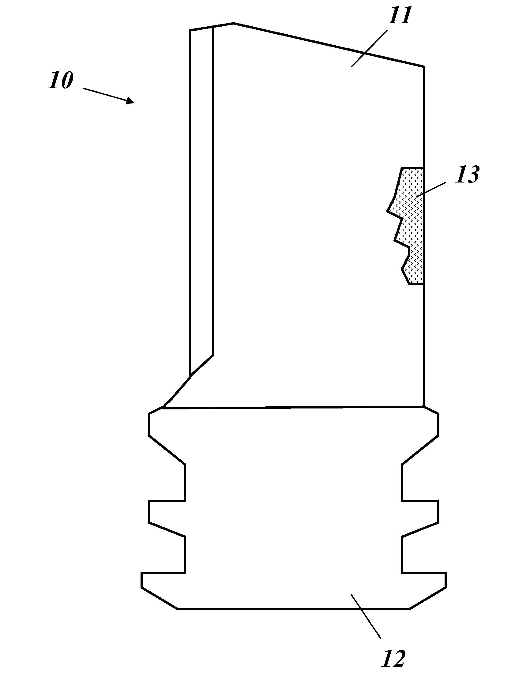
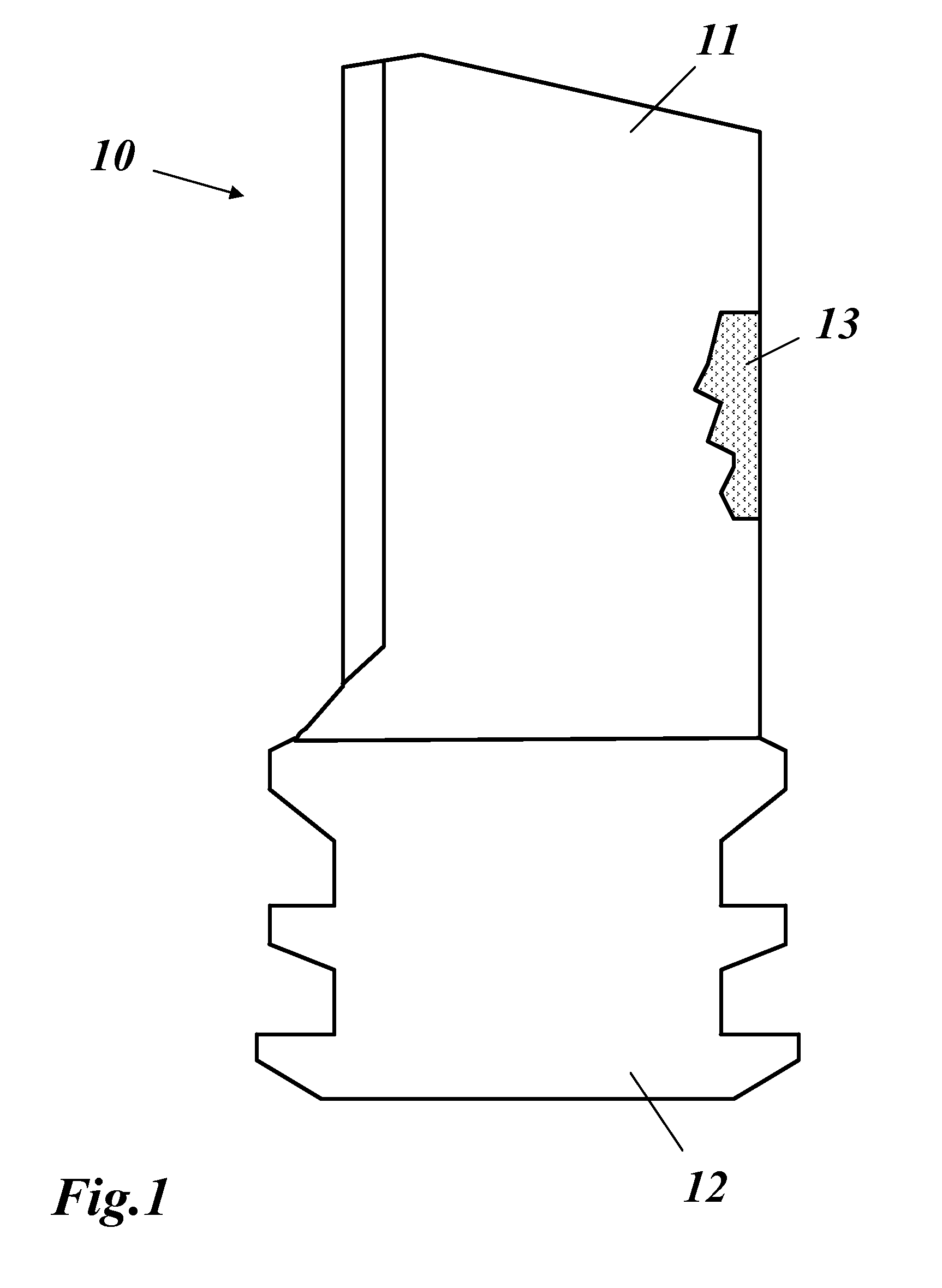
[0041]The method starts with the damaged gas turbine component an example of which is shown in FIG. 1. The gas turbine component 10 in this figure has the form of a turbine blade with an airfoil 11 and a root 12. This gas turbine component 10 is damaged as it shows a damaged area 13 at one of the edges of the airfoil 11.

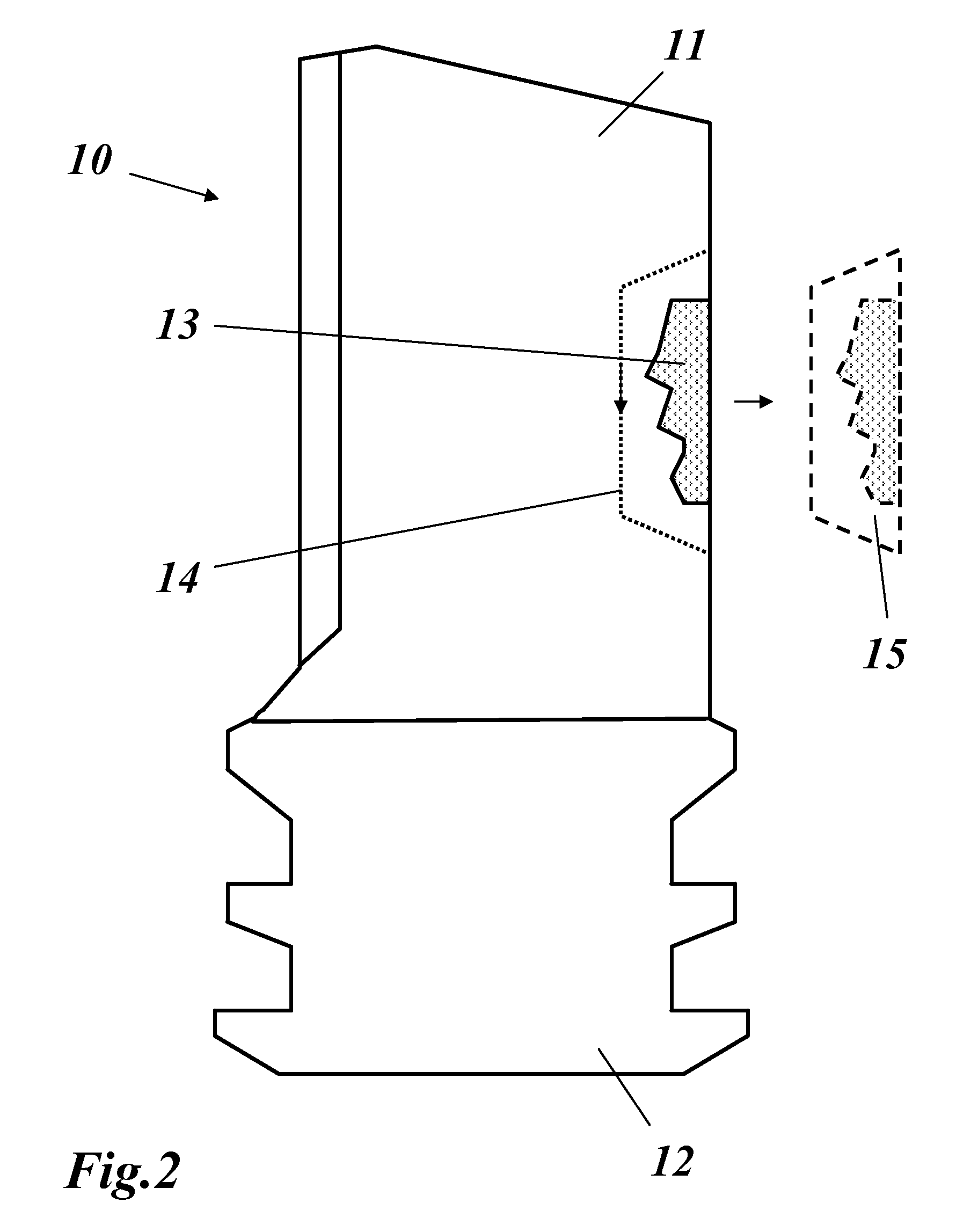
[0042]As shown in FIG. 2 the heavily damaged section or area 13 on the ex-service gas turbine component 10 is removed using a machin...


PUM

PropertyMeasurementUnit
inlet temperaturesaaaaaaaaaa
thicknessaaaaaaaaaa
gap widthaaaaaaaaaa

Abstract

A method for repairing an ex-service gas turbine component (10) includes the steps of: removing a damaged section (13) from the gas turbine component (10), manufacturing a 3-D article, which fits in the gas turbine component (10) to replace the removed damaged section (13), and joining the gas turbine component (10) and the 3-D article inserted therein. Reduced cost, improved flexibility and productivity, and simplified handling are achieved by removing the damaged section (13) in the form of a cut-out section along a split line (14) as one single cut-out piece (15), measuring the cut-out piece (15) to obtain the actual non-parametric geometry data set of the cut-out piece (15), and manufacturing the 3-D article based on the geometry data set of the cut-out piece (15).

Description

[0001]This application claims priority under 35 U.S.C. §119 to U.S. Provisional application no. No. 61 / 256,399, filed 30 Oct. 2009, the entirety of which is incorporated by reference herein.BACKGROUND[0002]1. Field of Endeavor[0003]The present invention relates to the technology of gas turbines, and also to a method for repairing a gas turbine component.[0004]2. Brief Description of the Related Art[0005]Today, gas turbines have turbine inlet temperatures of more than 1400° C. Accordingly, the components of those gas turbines such as blades, vanes or liners are exposed to a high thermal load and mechanical stress. As those components are usually made of expensive high-temperature resistant materials, it is desirable to repair those components, when damaged, instead of replacing them. However, the repair of damaged gas turbine components is of limited quality, when the damaged section is removed and an insert is manufactured to fit into the removed region, as the insert has to be manu...

Claims


Application Information

Patent Timeline
Patent Type & Authority Applications(United States)
IPC IPC(8): B23P17/00
CPCB22F7/062B22F2999/00B23K2201/001B23P6/005F01D5/005Y10T29/49229F05D2230/13F05D2250/20F05D2230/80B22F3/1055B23K2101/001Y02P10/25B22F10/28
Inventor STANKOWSKI, ALEXANDERHOVEL, SIMONERICKENBACHER, LUKASHOBEL, MATTHIASAMBROSY, GUNTER
Owner ALSTOM TECH LTD
Learn More