
Method for transmitting physical layer id information

a physical layer and information technology, applied in the field of transmitting cell identifier (id) information, can solve the problems of time latency and unnecessary power consumption of u

Inactive Publication Date: 2011-04-28
LG ELECTRONICS INC
View PDF3 Cites 16 Cited by
  • Summary
  • Abstract
  • Description
  • Claims
  • Application Information

AI Technical Summary

Benefits of technology

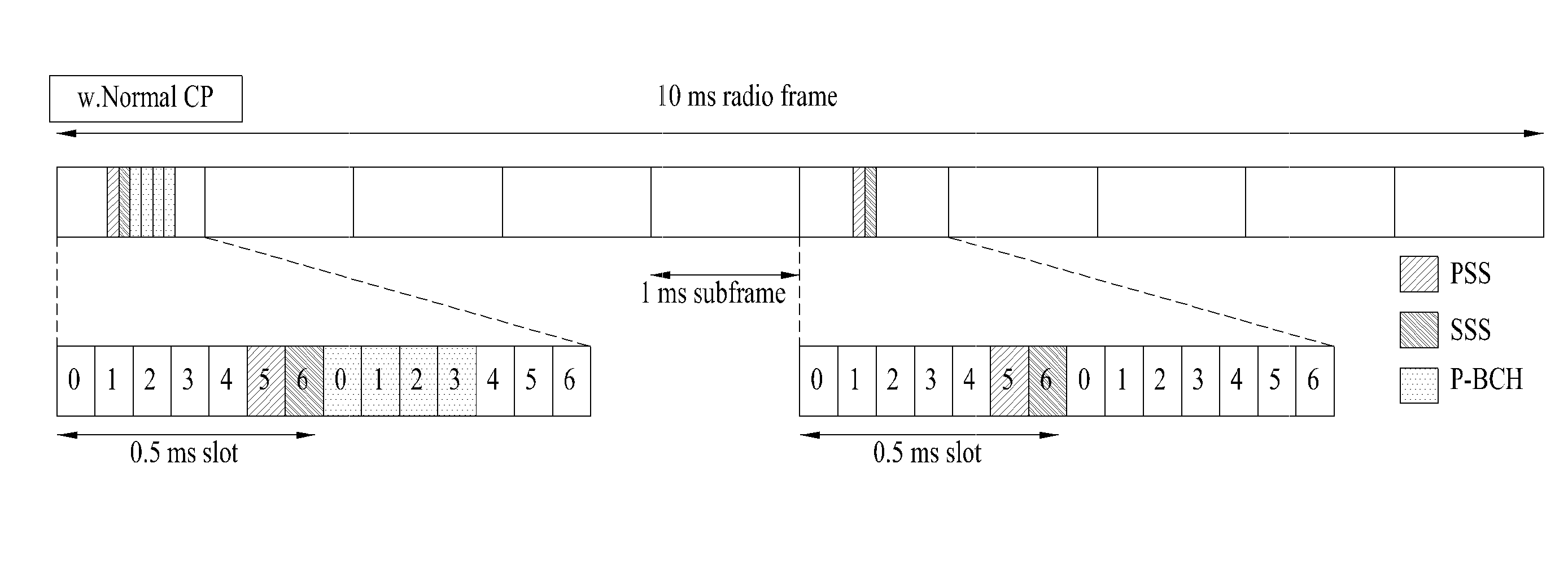
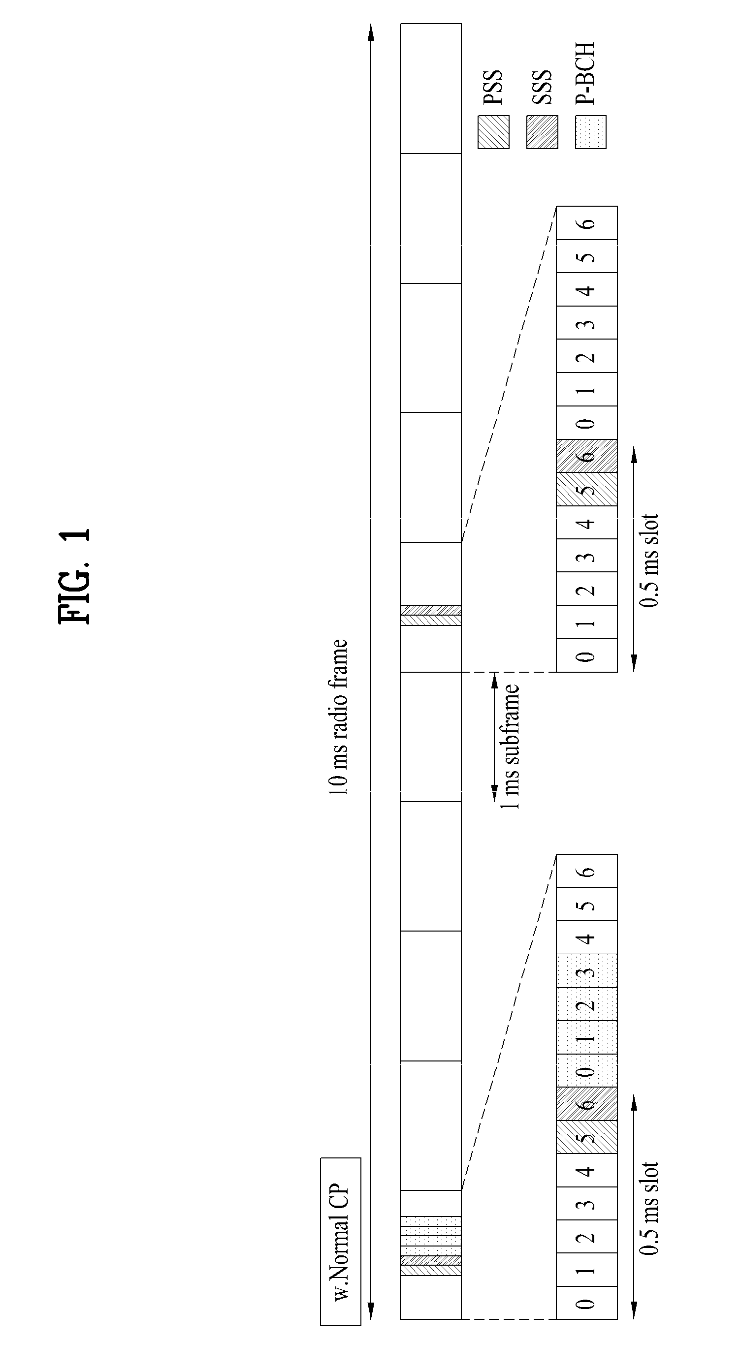
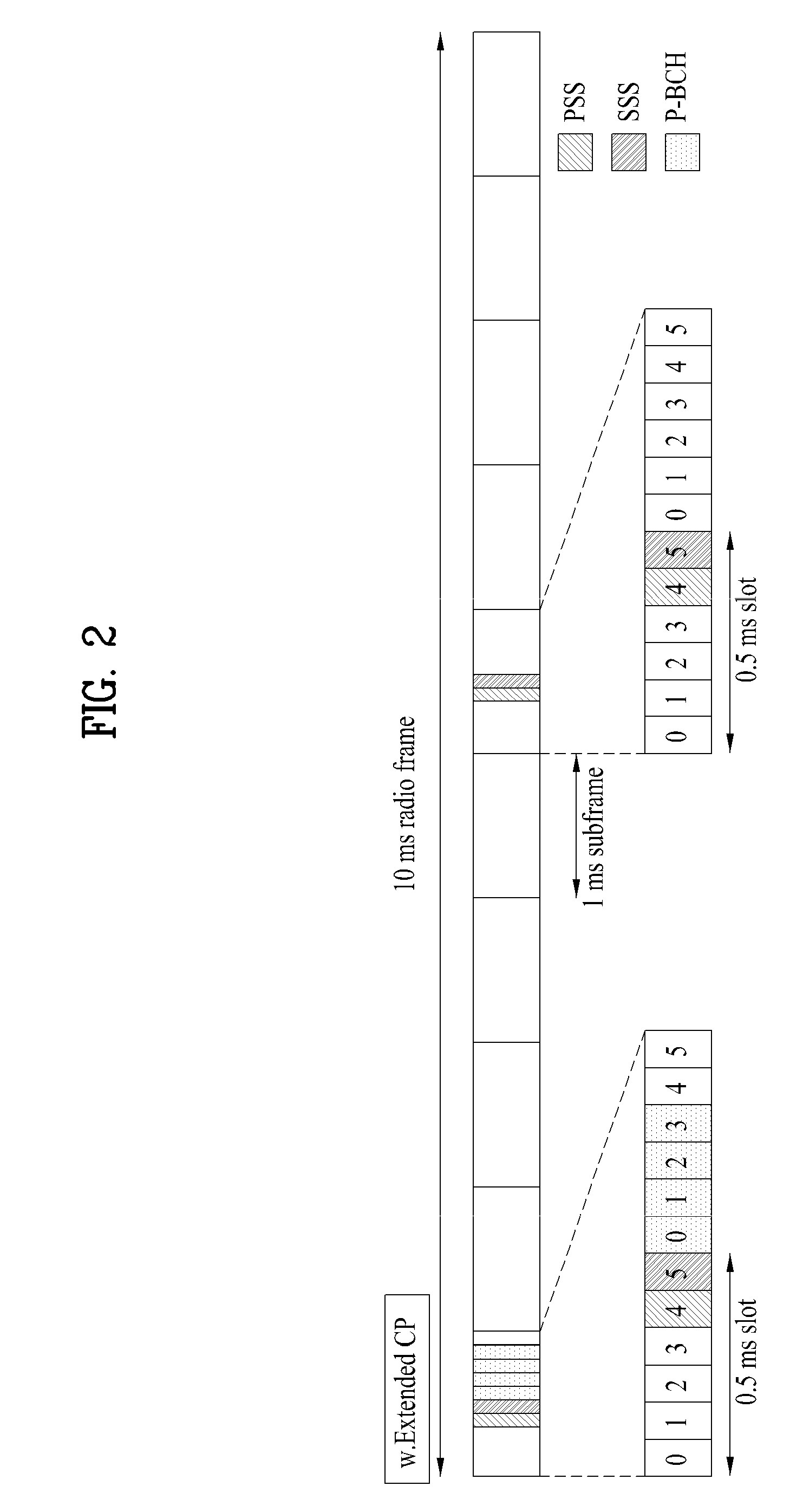
The present invention provides a method for transmitting physical layer cell ID information by increasing the number of existing cell IDs and searching for a CSG cell during initial cell search. This method allows for easier identification of a CSG cell and service property information of the serving cell. The physical layer cell ID information may represent cell ID information of a serving cell and service property information of the serving cell. The method may involve transmitting a Primary Synchronization Signal (PSS) and a Secondary Synchronization Signal (SSS) as two SSCs, where the SSS is transmitted after the PSS. The SSS may be transmitted based on a combination of a first segment and a second segment. The physical layer cell ID information may represent information indicating whether a serving cell is a CSG cell or an RS cell, an MBMS indicator, or a hot spot indicator. The method may also involve performing different phase modulation schemes on the two SSCs to indicate different types of cells. Overall, this invention provides a more efficient and effective method for transmitting physical layer cell ID information.

Problems solved by technology

The most challenging issue at this stage of standardization is to define a cell ID for a UE to identify whether a cell is a CSG cell or a non-CSG cell in an early phase of a cell identification process.
If the interpreted higher-layer ID indicates a CSG cell inaccessible to the UE, the UE has consumed unnecessary power and has experienced time latency.

Method used


Image

  • Method for transmitting physical layer id information
  • Method for transmitting physical layer id information
  • Method for transmitting physical layer id information

Examples


Embodiment Construction

[0046]Reference will now be made in detail to the preferred embodiments of the present invention with reference to the accompanying drawings. The detailed description, which will be given below with reference to the accompanying drawings, is intended to explain exemplary embodiments of the present invention, rather than to show the only embodiments that can be implemented according to the invention.

[0047]The following detailed description includes specific details in order to provide a thorough understanding of the present invention. However, it will be apparent to those skilled in the art that the present invention may be practiced without such specific details. In some instances, known structures and devices are omitted or are shown in block diagram form, focusing on important features of the structures and devices, so as not to obscure the concept of the present invention. The same reference numbers will be used throughout this specification to refer to the same or like parts.

[00...


PUM


Abstract

A method for transmitting IDs of cells of a specific type as physical cell ID information in addition to existing cell ID information is disclosed. For transmission of the physical cell ID information, the number of cell IDs used in transmitting the existing cell ID information on a synchronization channel is increased or a part of existing cell IDs are reserved for transmitting the additional specific-cell ID information. If the number of cell IDs is to be increased, the number of cell ID groups related to a secondary synchronization channel is increased in a manner that removes ambiguity and collision, a cell ID related to a primary synchronization channel is added, which satisfies conjugate symmetry, information is transmitted based on a transmission timing relationship between a primary synchronization code and a secondary synchronization code, or a scrambling scheme is modified. When a part of the existing cell IDs are reserved, conjugate symmetry is also considered in relation to a primary synchronization channel and ambiguity and collision are also considered in relation to a secondary synchronization channel.

Description

BACKGROUND OF THE INVENTION[0001]1. Field of the Invention[0002]The present invention relates to a method for transmitting cell Identifier (ID) information in a wireless communication system, and more particularly, to a method for efficiently transmitting additional cell ID information, while minimizing influence on a legacy system.[0003]2. Discussion of the Related Art[0004]A cell ID identifies a cell covering a specific area within a wireless network. The specific area includes at least one Base Transceiver Station (BTS) or Node B that controls wireless operations within its coverage area and provides connectivity between the network and a Mobile Station (MS) or User Equipment (UE) via an air interface. The BTS or Node B or eNode B is an access point for indoor or / and outdoor coverage.[0005]For home coverage, the access point is known as a femtocell Base Station (BS), a Home Node B (HNB), an evolved Home Node B (eHNB), or a Closed Subscriber Group (CSG) BS which is a smaller cellu...

Claims


Application Information

Patent Timeline
Patent Type & Authority Applications(United States)
IPC IPC(8): H04B7/00
CPCH04J11/0079H04L25/03866H04W56/00
Inventor HAN, SEUNG HEEKWON, YEONG HYEONVUJCIC, DRAGANKIM, DONG CHEOLMOON, SUNG HOKWAK, JIN SAMNOH, MIN SEOKLEE, HYUN WOO
Owner LG ELECTRONICS INC
Learn More