
Radial Compressor

Inactive Publication Date: 2011-04-28
MANN HUMMEL GMBH
View PDF13 Cites 27 Cited by
  • Summary
  • Abstract
  • Description
  • Claims
  • Application Information

AI Technical Summary

Benefits of technology

[0006]It is therefore an object of the present invention to propose a radial compressor of the aforementioned kind where a significant noise reduction is realized at the housing in a simple way.

Problems solved by technology

In case of exhaust gas turbo chargers the housing is comprised of metal because of the high temperatures and high pressures.
When operating the compressor in particular at high engine speeds significant noise is developed that, because of the high frequencies, is perceived as disturbing and unpleasant.
Moreover, there exist numerous noises variable with regard to their frequency spectra that are caused, for example, by shaft imbalances, pulsation phenomena, aerodynamic effects (for example, flow about the compressor or turbine vanes).

Method used


Image

  • Radial Compressor
  • Radial Compressor
  • Radial Compressor

Examples


Embodiment Construction

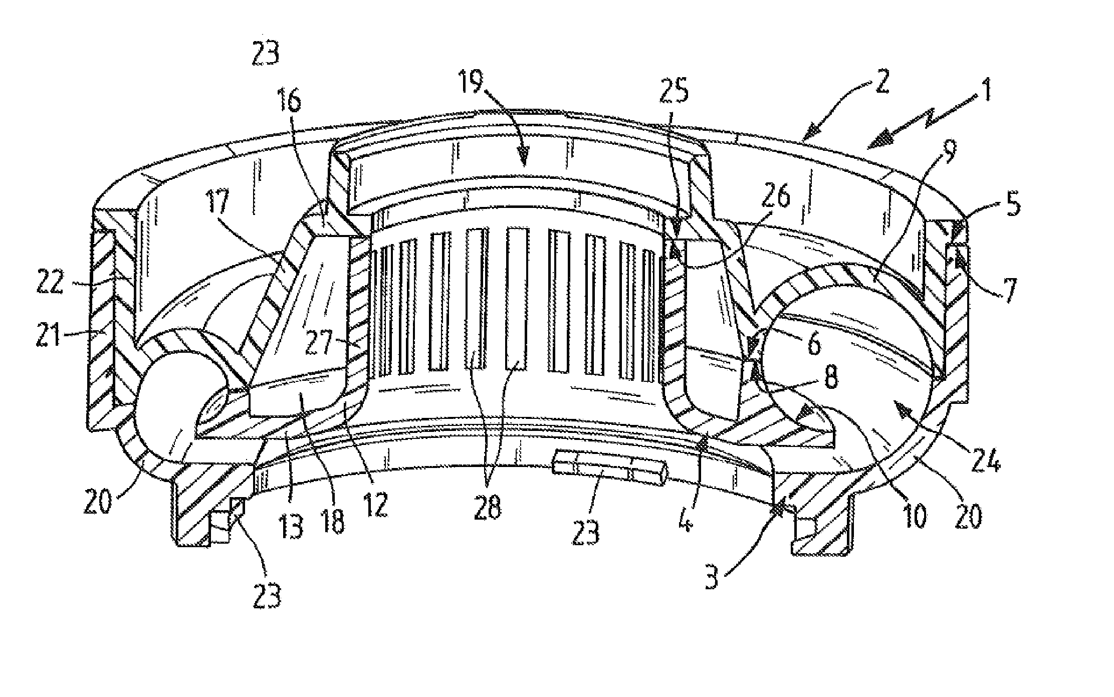
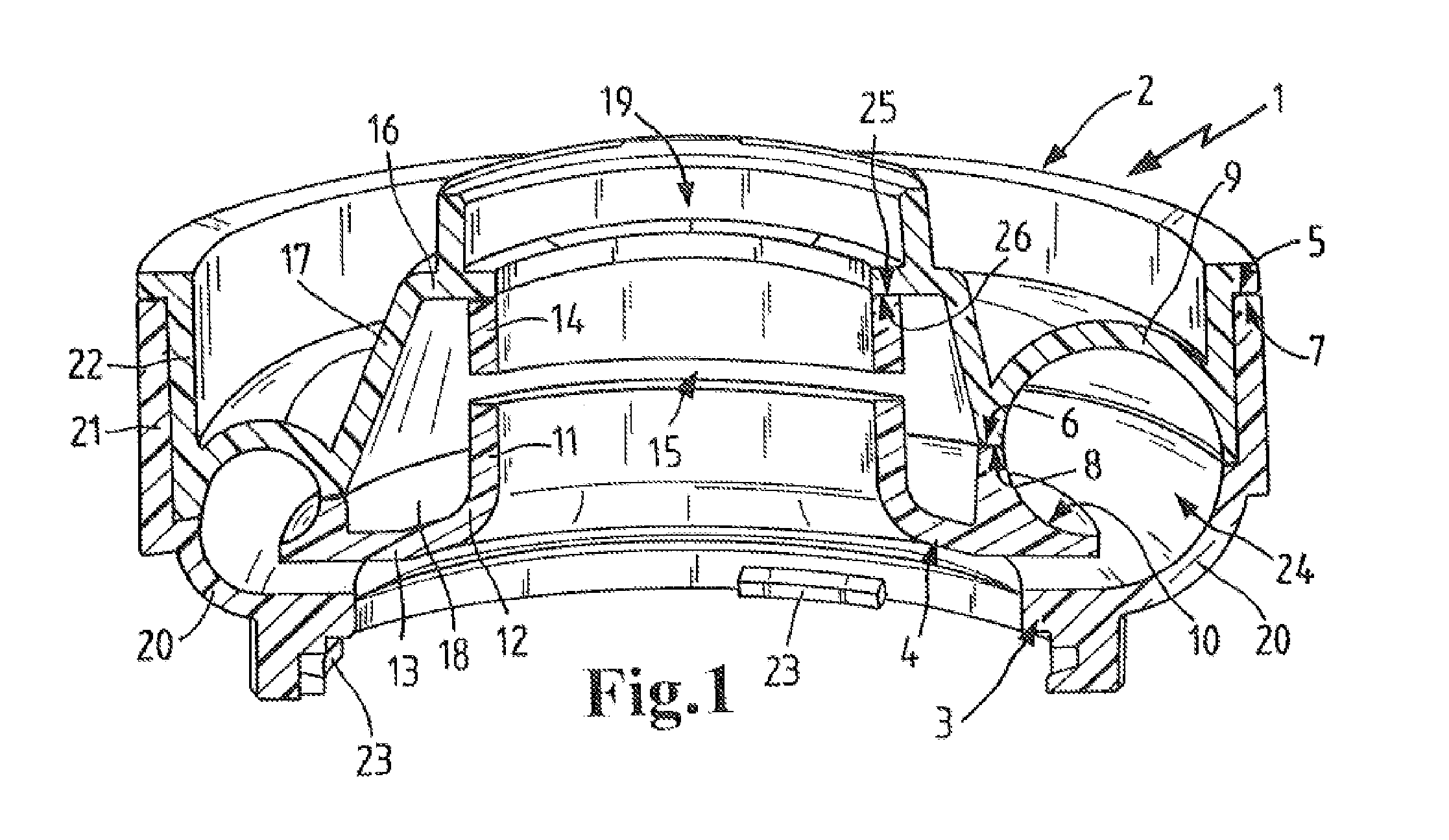
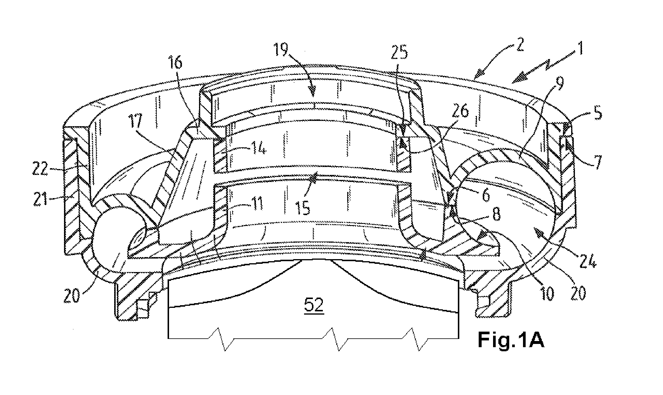
[0021]FIG. 1 shows a housing 1 that is comprised of three housing parts wherein between the top part 2 and the bottom part 3 a central part 4 is arranged. These housing parts 2, 3, 4 are comprised of a thermoplastic synthetic material, for example, PPS (polyphenyl sulfide). On the top part 2 there are two annular joining or connecting surfaces 5, 6 wherein on the connecting surface 5 an end face 7 of the bottom part 3 and on the connecting surface 6 a contact surface 8 of the central part 4 are resting. The connecting surface 5 and the end face 7 as well as the connecting surface 6 and the contact surface 8 form welding zones, respectively, where the parts are integrally joined or bonded. FIG. 1A shows the radial compressor housing of FIG. 1 including a schematic depiction of a compressor wheel 52 rotatably supported in the housing.

[0022]On the top part 2 a curved portion 9 that is open in downward direction is formed that extends in an annular shape and is widening in the circumfer...


PUM


Abstract

A radial compressor for a turbo charger has a housing with an inflow passage and a spiral passage. A compressor wheel is supported rotatably in the housing. The housing has at least two housing parts between which a cavity is formed. At least one opening is provided in the inflow passage, wherein the at least one opening fluidically connects the cavity with the inflow passage.

Description

CROSS REFERENCE TO RELATED APPLICATIONS[0001]This application claims the benefit under 35 USC 119 of foreign application DE 10 2009 051 104.0 filed in Germany on Oct. 28, 2009, and which is hereby incorporated by reference in its entirety.BACKGROUND OF THE INVENTION[0002]The invention concerns a radial compressor, especially for a turbo charger, comprising a housing with an inflow passage and a spiral passage, wherein in the housing a compressor wheel is rotatably supported. The housing is comprised of at least two housing parts between which at least one cavity is formed.[0003]Turbo engines are generally used in connection with internal combustion engines in order to compress, for the purpose of increasing performance and efficiency, the sucked-in fresh air to a higher pressure level. In case of exhaust gas turbo chargers the housing is comprised of metal because of the high temperatures and high pressures. Moreover, mechanically or electrically driven compressors are known whose h...

Claims


Application Information

Patent Timeline
IPC IPC(8): F04D29/66F01D9/02
CPCF01D25/26F04D29/665F04D29/4213F05D2220/40F02M35/1261F02M35/1266
Inventor SCHICK, HEDWIGHANISCH, ROBERT
Owner MANN HUMMEL GMBH
Learn More