Metamaterial lens feed for multiple beam antennas

a technology of metal materials and antennas, applied in the field of multibeam reflector antenna systems, can solve the problems of affecting the pattern performance on the ground, limiting the effectiveness of the antenna system, and high cost, and achieve the effect of reducing the mutual coupling of feed signals

Active Publication Date: 2011-04-28
LOCKHEED MARTIN CORP
View PDF12 Cites 78 Cited by
  • Summary
  • Abstract
  • Description
  • Claims
  • Application Information

AI Technical Summary

Benefits of technology

[0011]Concordant and consistent with the present invention, a multiple beam reflector antenna that provides an increased effective feed horn aperture and a reduced spill over loss capable of simultaneous operation over widely separated transmit and receive bands has surprisingly been discovered. The multiple beam reflector antenna includes at least one reflector, a plurality of feed horns for feeding the at least one reflector, and a metamaterial lens interposed between the plurality of feed horns and the at least one reflector. The metamaterial lens provides an overlapping element distribution from at least two feed horns of the plurality of feed horns. In one embodiment, the metamaterial lens has an index of refraction between about zero and about one. In another embodiment, the metamaterial lens is comprised of one or more of low index materials (LIM), zero index materials (ZIM), and graded index (GRIN) materials that may have an index of refraction below one or above one.
[0012]In another embodiment, a lower surface of the metamaterial lens is adjacent the feed horn apertures of at least two adjacent feed horns. The lower surface of the metamaterial lens includes a notch disposed between the at least two adjacent feed horns to provide separation between the feed horn apertures of the at least two adjacent feed horns to reduce mutual coupling of feed signals therefrom.

Problems solved by technology

For each individual reflector, feed horn efficiency and directivity limits the effectiveness of the antenna system.
In particular, an inadequately directive feed horn causes an energy spill over the reflector that can account for up to a 3 dB gain loss, and can also affect pattern performance on the ground.
For example, Luneberg lenses having graded indices of refraction using a regular dielectric are well known, but are typically large, heavy, and have a high cost, and are therefore impractical for space applications.
However, the active lens design concept is in a preliminary stage, and in any event, is only applicable to transmit MBAs.

Method used


Image

  • Metamaterial lens feed for multiple beam antennas
  • Metamaterial lens feed for multiple beam antennas
  • Metamaterial lens feed for multiple beam antennas

Examples


Embodiment Construction

[0022]The following detailed description and the appended drawing describe and illustrate various embodiments of the invention. The description and drawings serve to enable one skilled in the art to make and use the invention, and are not intended to limit the scope of the invention in any manner.

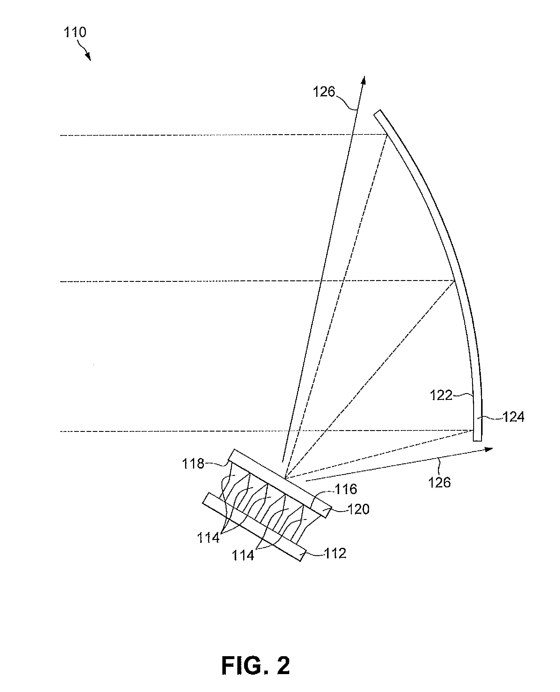
[0023]A multiple beam antenna (MBA) reflector system 110 constructed according to the present invention is shown in FIG. 2. A signal feed network 112 includes a plurality of feed horns 114 that each terminate in a feed horn aperture 116. It is understood that each feed horn 114 may be individually optimized for frequency and power as is known in the art, and may be configured for transmission or for reception of signals within a desired frequency band, or for both. It is further understood that the feed horns 114 may generate different or identical waveforms, as desired. Each feed horn aperture 116 abuts a lower surface 118 of a metamaterial lens 120, embodiments of which are further descri...


PUM


Abstract

A multiple beam reflector antenna includes at least one reflector, a plurality of feed horns for feeding the at least one reflector, and a metamaterial lens interposed between the plurality of feed horns and the at least one reflector. The metamaterial lens may provide an overlapping element distribution from at least two feed horns of the plurality of feed horns. In one embodiment, the metamaterial lens has an index of refraction between about zero and about one.

Description

CROSS-REFERENCE TO RELATED APPLICATIONS[0001]The present application claims priority to U.S. Provisional Application Ser. No. 61 / 254,167 filed Oct. 22, 2009, incorporated by reference herein in its entirety.STATEMENT REGARDING GOVERNMENT SPONSORED RESEARCH OR DEVELOPMENT[0002]Not Applicable.FIELD OF THE INVENTION[0003]The present invention relates antenna systems. In particular, the present disclosure relates to multibeam reflector antenna systems for use in satellite communication systems.BACKGROUND OF THE INVENTION[0004]Over the last few years, there has been a tremendous growth in the use of multiple-beam antenna (MBA) systems for satellite communications. For example, MBAs are currently being used for direct-broadcast satellites (DBS), personal communication satellites (PCS), military communication satellites, and high-speed Internet applications. These antennas provide mostly contiguous coverage over a specified field of view on Earth by using high-gain multiple spot beams for ...

Claims


Application Information

Patent Timeline
IPC IPC(8): H01Q19/08
CPCH01Q15/02H01Q15/10H01Q15/0086H01Q19/08H01Q19/17H01Q19/06
Inventor LIER, ERIK
Owner LOCKHEED MARTIN CORP
Why Eureka
Try Eureka