
Image processing apparatus and method, and computer-readable storage medium

a technology of image processing and processing apparatus, applied in the field of image processing apparatus and image transformation processing method, can solve the problems of difficult to extract and classify only inter-individual differences while ignoring photographic, and the influence does not always appear uniformly in the entire face region, so as to achieve the effect of not increasing parameters and processing loads

Active Publication Date: 2011-04-21
CANON KK
View PDF15 Cites 94 Cited by
  • Summary
  • Abstract
  • Description
  • Claims
  • Application Information

AI Technical Summary

Benefits of technology

[0019]The present invention has been conceived in light of the above problems. A preferred embodiment of the invention provides a method and apparatus with which it is possible to perform various types of spatial transformation processing such as image deformation, linear spatial filter processing and luminance distribution correction processing, without increasing parameters and processing loads.

Problems solved by technology

One of the problems that arises when identifying individuals using face images or the like is that variations due to other factors are larger than inter-individual variations.
For this reason, it can be said that it is very difficult to extract and classify only inter-individual differences while ignoring photographic conditions and other variations.
Even when variations as described above occur in the data of a plurality of face images obtained by capturing an individual, the influence does not always appear uniformly in the entire face region.
However, the method that selectively uses local regions uses only a part of information appearing in an image, which is disadvantageous in terms of identification accuracy.
In such a case, the methods described above have the following problems.
According to the method disclosed in Non-Patent Document 1, the technique for deforming local regions is limited to affine transformation.
However, because human faces have a complex shape, the errors created by treating local regions as planes are not small.
Furthermore, in addition to the problem of orientation variations, this method has the problem in that it is not possible to correct physical shape deformations due to changes in facial expressions.
In addition, it is necessary to perform deformation processing prior to similarity calculation using registered images, which increases processing loads.
The Lucas-Kanade method is originally a technique for finding a correspondence point between two images, and therefore it is possible to represent arbitrary deformations as a correspondence point list, for example, by extending the technique of this document, but in this case as well, problems of increased processing loads and increased parameters arise.
According to the method of Non-Patent Document 3, although scaling is performed in units of local regions, extraction is always performed in the shape of a rectangle, and the shape is not deformed, and therefore there is a limit to the improvement of similarity for each region.
There are also concerns over the increase of processing loads due to the additional scaling processing.
In addition, in order to flexibly cope with various kinds of deformations, it is necessary to increase the number of feature points to which deformation vectors are attached, and in this case, the increase of memory for storing parameters is the problem.
However, all of the above-described techniques require addition of filter processing, and thus are problematic in that the size and processing loads of the processing apparatus increase.

Method used


Image

  • Image processing apparatus and method, and computer-readable storage medium
  • Image processing apparatus and method, and computer-readable storage medium
  • Image processing apparatus and method, and computer-readable storage medium

Examples


embodiment 1

Description of Overall Block Diagram

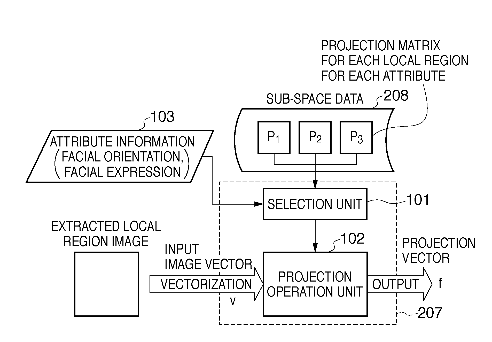
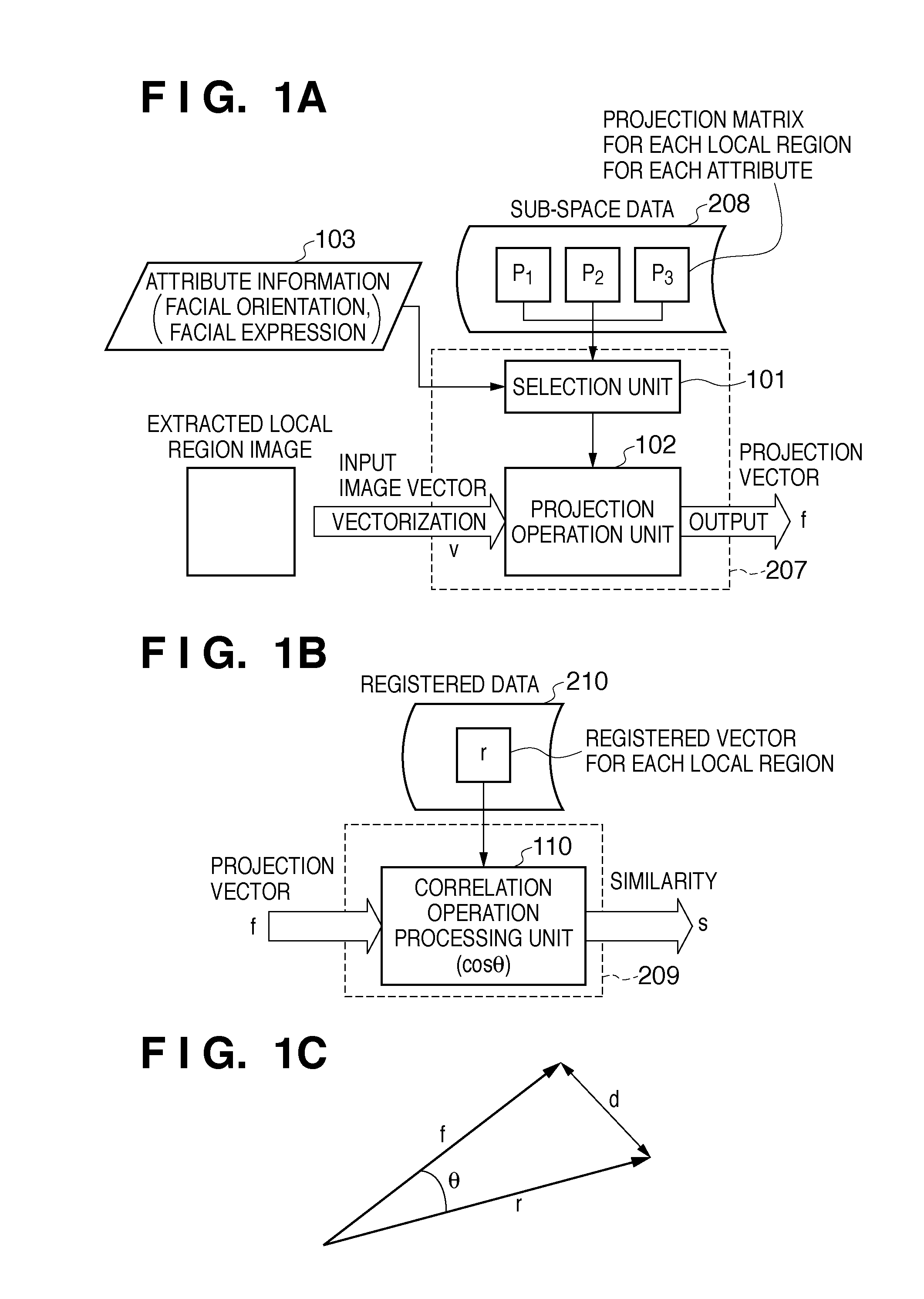
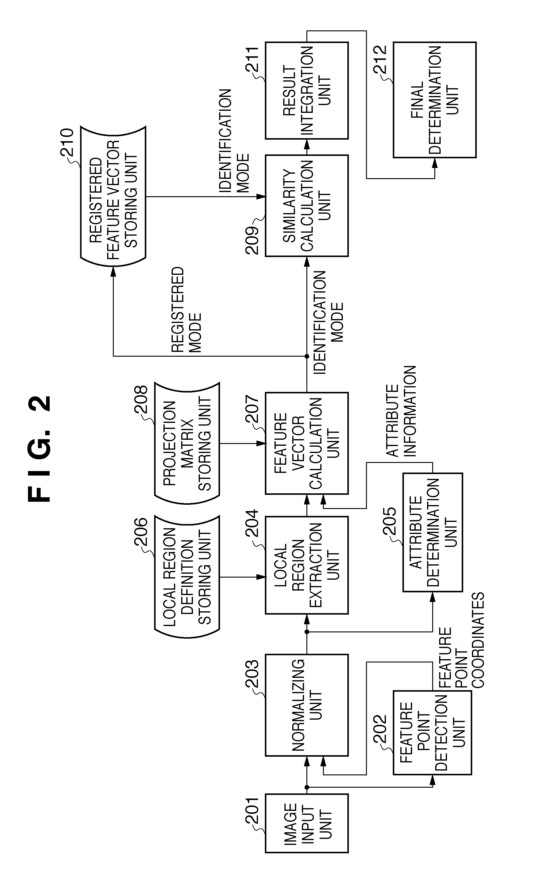
[0045]FIG. 2 is a block diagram showing a configuration of a face image recognition processing apparatus to which an embodiment of an image processing apparatus of the present invention is applied. Each block is implemented as, for example, a dedicated hardware processing circuit, and is connected with a predetermined I / F. Although not shown, there is a control unit that performs overall control of constituent units and causes the units to execute a series of processes for registration or identification.

[0046]An image input unit 201 receives an input of a face image extracted in a predetermined size by pre-processing (not shown). The image from which the face image is extracted is, for example, electronic data acquired by a camera apparatus. Such a camera apparatus is constituted by, for example, an optical system, a photoelectric conversion device such as a CCD (charge coupled device) sensor, a driver circuit, an AD converter, a signal processing...

embodiment 2

[0147]In Embodiment 1, deformation processing is used as the spatial transformation processing, but the present invention is not limited thereto. In Embodiment 2, an example will be described in which linear spatial filter processing is used as the spatial transformation processing. The spatial transformation matrix at this time is a filter processing matrix. More specifically, the spatial transformation matrix of Embodiment 2 is a matrix with which it is possible to perform filter processing for an entire local region with a single operation, or in other words, an all-pass filter processing matrix.

[0148]FIG. 13A shows a filter kernel of a Gaussian filter (smoothing filter) having 3×3 coefficients that is a type of linear spatial filter. The coefficients in the various blocks each represent the reference ratio between the pixel at the center position of the block and the surrounding pixels (actually, 1 / 16 of that value is stored). In order to cause such filter coefficients to operat...

embodiment 3

Luminance Distribution Correction

[0153]The present invention can also be applied to processing for correcting a luminance distribution within a local region. For example, in the case of the human face, when there is a light source in either the right or left direction, the shadow from the nose is likely to appear. Accordingly, in the case of estimating the light source direction as a variation attribute, it may be effective to perform luminance distribution correction such as increasing the luminance of the pixels in the regions located in the shadow of the nose.

[0154]Reference numeral 1701 in FIG. 15 is a luminance correction distribution table of a local region in the case of a given variation attribute, and the coefficient at each position indicates a luminance transformation coefficient that is multiplied with the corresponding pixel. In other words, the pixels in the right side region of 1701 are likely to be the shadow, and thus larger coefficients are set to increase the lumi...


PUM


Abstract

An image processing apparatus classifies a variation of a target object included in an image from a specific state as one of a plurality of types of attributes, and holds, for each variation attribute, a correction parameter for spatial transformation that corrects the target object to the specific state. The image processing apparatus generates an input image vector by vectorizing at least a partial region of the input image, and determines a variation attribute by detecting a variation of the target object from the specific state in the input image. Then, the image processing apparatus generates a transformed image vector by performing the spatial transformation on the input image vector, using a correction parameter selected based on the determined variation attribute from among the correction parameters held for respective variation attributes.

Description

BACKGROUND OF THE INVENTION[0001]1. Field of the Invention[0002]The present invention relates to an image processing apparatus and an image transformation processing method.[0003]2. Description of the Related Art[0004]Conventionally, identification technology for identifying people based on physical features such as fingerprints, palm prints, veins, and irises, so-called biometric authentication technology has been developed. Biometric authentication technology includes many processes that are performed using images acquired by a photoelectric conversion imaging apparatus, such as a digital camera, or data that has been converted to two-dimensional space data corresponding to an image. Face authentication technology using face images, among others, is one of the technologies that is attracting particular attention because face authentication technology involves the same actions as those usually performed by people when identifying other people, and there is less of a sense of resist...

Claims


Application Information

Patent Timeline
Patent Type & Authority Applications(United States)
IPC IPC(8): G06K9/68
CPCG06K9/00248G06K9/00315G06T3/0093G06K9/6206G06V40/165G06V40/176G06V10/754G06T3/18
Inventor ITO, YOSHINORIKATO, MASAMIYAMAMOTO, TAKAHISA
Owner CANON KK
Learn More