Lens array set and projection apparatus

Inactive Publication Date: 2011-04-21
DELTA ELECTRONICS INC
View PDF6 Cites 3 Cited by
  • Summary
  • Abstract
  • Description
  • Claims
  • Application Information

AI Technical Summary

Benefits of technology

[0015]According to the above description, the first lens unit of the present invention adopts the appropriate shape to modulate the light projection shape into a length-to-width ratio conforming to that of the micro-display device to prevent light loss. Moreover, the correspondence relationship between the first lens units and the second lens units further allows for uniform distribution of the projected light.

Problems solved by technology

However, when a square light is projected onto a non-square micro-display device such as a digital micromirror device (DMD), a liquid crystal display (LCD), or a liquid crystal on silicon (LCOS) (because the micro-display device must be of a specific length-to-width ratio to fit display requirements), the shape of the light fails to conform to that of the micro-display device, thereby leading to reduction in the light availability.
By means of such optical elements, the light projection shape of the LED can be altered to satisfy an aspect ratio when being projected onto the micro-display device; however, when the light passes through the aforesaid optical elements, the light source shape tends to be altered, leading to problems such as a mismatch between the light source shape with the projection lens opening.
Furthermore, when a single lens is used to focus, light distribution non-uniformity can occur when the light is projected onto the micro-display device through the single lens.
The non-uniformity results in too much luminance on the central portion of the resulting image but insufficient luminance on the peripheral portions.
However, as described above, the lens units 131 must be designed to match the shapes of the lens units 141, so it is difficult for a lens array set to alter the light projection shape of the LEDs 12.

Method used


Image

  • Lens array set and projection apparatus
  • Lens array set and projection apparatus
  • Lens array set and projection apparatus

Examples


Embodiment Construction

[0028]Hereinbelow, the lens array set of the present invention will be explained with reference to embodiments thereof. However, it should be appreciated that these embodiments are not intended to limit the present invention to any specific environment, applications or particular implementations described in these embodiments. Therefore, description of these embodiments is only for the purpose of illustration rather than limitation of the present invention.

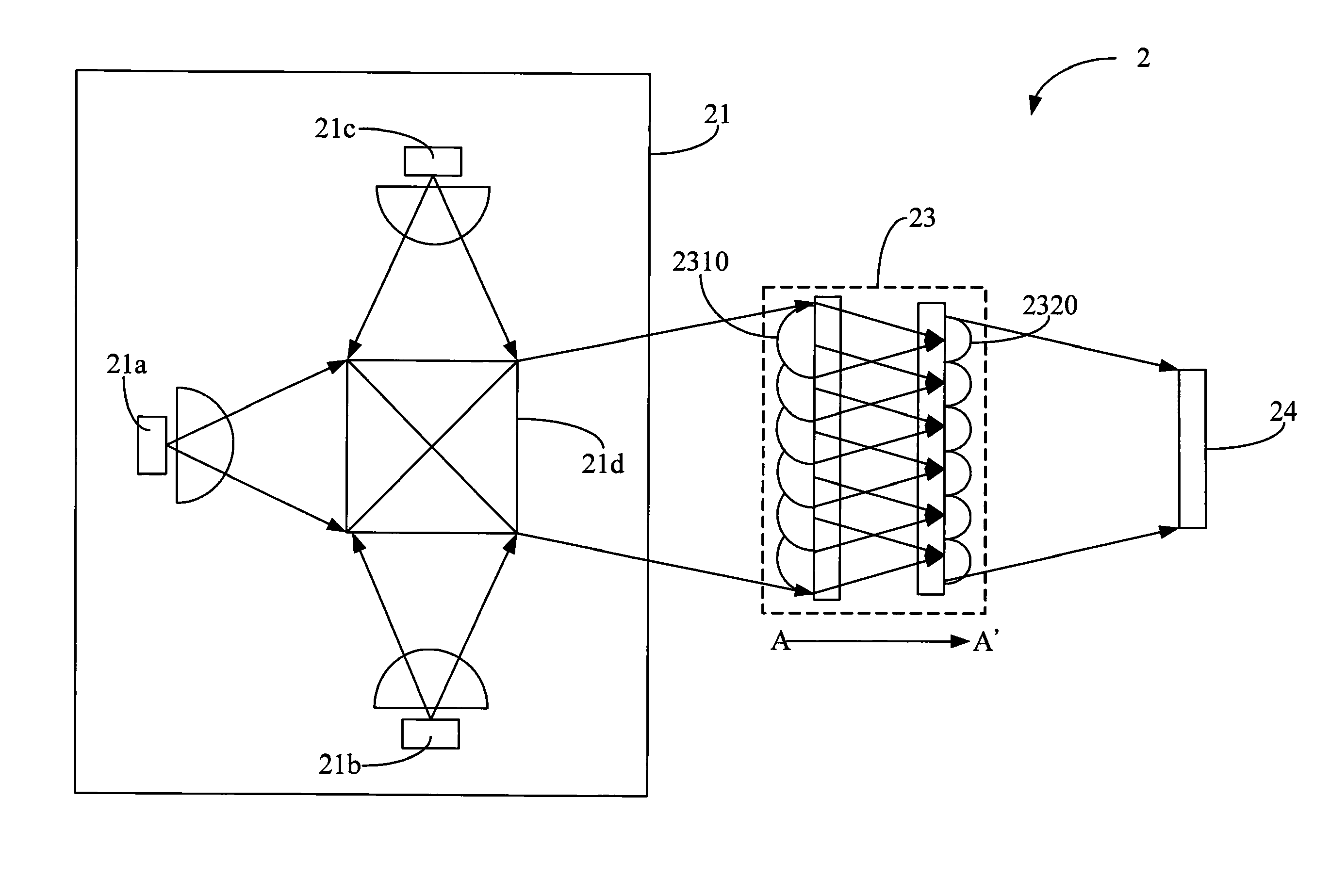
[0029]First, FIG. 2A illustrates a schematic view of a projection apparatus 2 of the present invention. The projection apparatus 2 comprises an LED light source module 21, a lens array set 23 and a micro-display device 24. The LED light source module 21 comprises a red LED 21a, a green LED 21b, a blue LED 21c and a light coupling component 21d. The LEDs 21a, 21b, 21c generate a light in a timed sequence, which is guided towards the lens array set 23 through the light coupling component 21d. It shall be appreciated that the interna...


PUM


Abstract

A lens array set for a projection apparatus is provided. The lens array set comprises a first lens array and a second lens array. The first lens array has a plurality of first lens units which are rectangle-shaped and a side thereof that defines the first direction. The second lens array, which is parallel with the first lens array, has a plurality of second lens units which has a rectangle shape and a side thereof that defines the second direction. Each of the second lens units is set correspondingly to each of the first lens units, and the center of each second lens unit and the center of each first lens unit are coaxial. A rotation angle is substantially defined between the first direction and the second direction depending on the difference between the rectangle shapes of the first and the second lens units. When adopting the present invention in the projection apparatus, the light source efficiently provides light for the micro-display.

Description

[0001]This application claims priority to Taiwan Patent Application No. 098135425 filed on Oct. 20, 2009.CROSS-REFERENCES TO RELATED APPLICATIONS[0002]Not applicable.BACKGROUND OF THE INVENTION[0003]1. Field of the Invention[0004]The present invention provides a lens set for a projection apparatus. In particular, the present invention provides a lens set for reducing light loss in a projection apparatus.[0005]2. Descriptions of the Related Art[0006]Due to advantages, such as a long service, life, low operation temperature and immediate switching capabilities, light emitting diodes (LEDs) have gradually replaced ultra high performance (UHP) mercury bulbs as light sources of projection apparatuses. When LEDs are adopted as light sources of the projection apparatus, the design and disposition of optical elements in the projection apparatus must also be considered to achieve desirable light availability and light distribution uniformity.[0007]With regards to light availability, most LED...

Claims


Application Information

Patent Timeline
IPC IPC(8): G03B21/14G02B27/12
CPCG02B27/0961G03B21/14G02B27/0966G03B21/208
Inventor HUANG, JUNE-JEI
Owner DELTA ELECTRONICS INC
Why Eureka
Try Eureka