
Image deblurring using a spatial image prior

Inactive Publication Date: 2011-04-21
MONUMENT PEAK VENTURES LLC
View PDF12 Cites 69 Cited by
  • Summary
  • Abstract
  • Description
  • Claims
  • Application Information

AI Technical Summary

Benefits of technology

[0030]This invention has the advantage that it produces deblurred images having a lower noise level than the sharp image, but having a higher sharpness level than the blurred image.
[0031]It has the additional advantage that it produces deblurred images having fewer ringing artifacts than prior art deblurring algorithms.

Problems solved by technology

This type of image blur is sometimes called “motion blur” or “smear.” Motion blur typically occurs when the light level in the image capture environment is dim, thus necessitating a long exposure time.
However, this is only effective when the subject is relatively close to the camera.
Additionally, many users find that flash photography provides a less satisfactory experience.
While much progress has been made in this area in recent years, the light sensitivity of currently available electronic image sensors is not high enough to prevent motion blur in many image capture environments.
One factor that reduces the light sensitivity of electronic image sensors is the use of color filters placed over the sensors to enable the formation of color images.
While this general approach is used today in most consumer digital cameras, the color filter array (CFA) has the undesirable effect of throwing away about ⅔ of the incident light, and therefore substantially reduces the photographic speed of the imaging system.
Although this system improves the light sensitivity over a single conventional image sensor, the overall complexity, size, and cost of the system is greater due to the need for two sensors and a beam splitter.
Furthermore, the beam splitter directs only half the light from the image to each sensor, limiting the improvement in photographic speed.
Blind deconvolution is an ill-posed problem, which is significantly more challenging.
The most challenging problem is single-image blind deblurring, which requires the simultaneous estimation of the deblurred image and the Point Spread Function (PSF) associated with the image blur.
As a result, the corresponding deconvolution becomes a well-posed problem.
The noise associated with the short exposure time image can be severe under low light condition, and therefore the deblurring results are highly depend on the performance of a denoising operation.
This deblurring approach is limited to image blur caused by defocus.

Method used


Image

  • Image deblurring using a spatial image prior
  • Image deblurring using a spatial image prior
  • Image deblurring using a spatial image prior

Examples


Embodiment Construction

[0037]In the following description, some embodiments of the present invention will be described in terms that would ordinarily be implemented as software programs. Those skilled in the art will readily recognize that the equivalent of such software may also be constructed in hardware. Because image manipulation algorithms and systems are well known, the present description will be directed in particular to algorithms and systems forming part of, or cooperating more directly with, the method in accordance with the present invention. Other aspects of such algorithms and systems, together with hardware and software for producing and otherwise processing the image signals involved therewith, not specifically shown or described herein may be selected from such systems, algorithms, components, and elements known in the art. Given the system as described according to the invention in the following, software not specifically shown, suggested, or described herein that is useful for implement...


PUM


Abstract

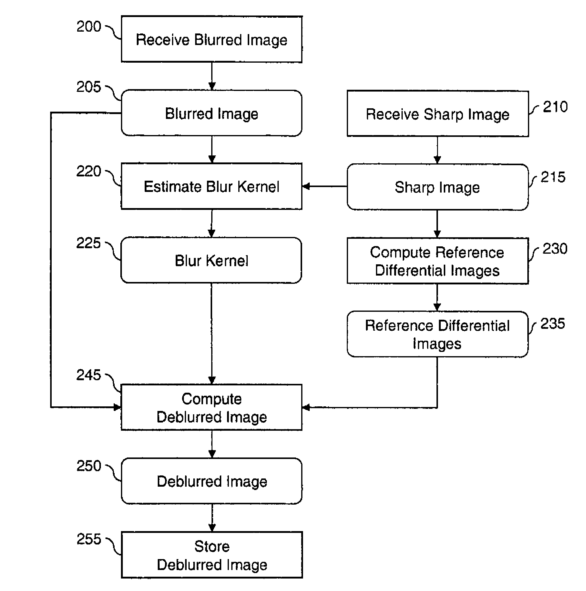
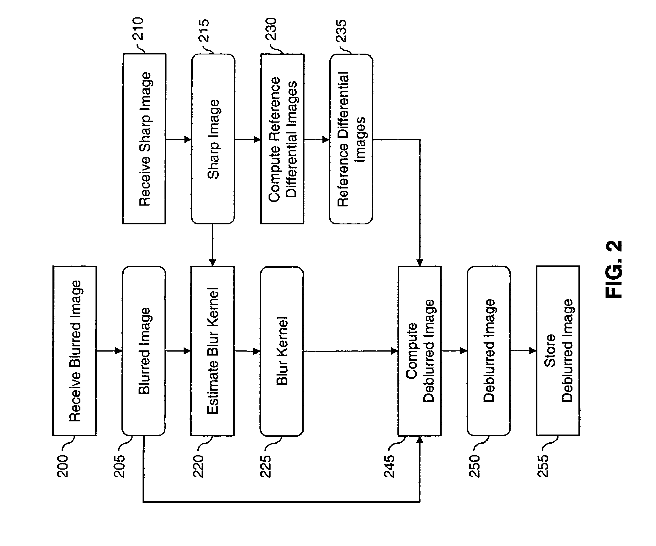
A method for determining a deblurred image, the method implemented at least in part by a data processing system and comprising: receiving a sharp image of a scene captured with a short exposure time; receiving a blurred image of the scene captured with a longer exposure time than the sharp image, wherein the blurred image has a higher level of motion blur and a lower level of image noise than the sharp image; determining a blur kernel responsive to the sharp image and the blurred image; determining one or more reference differential images responsive to the sharp image; determining a deblurred image responsive to the blurred image, the blur kernel and the one or more reference differential images; and storing the deblurred image in a processor-accessible memory system.

Description

CROSS-REFERENCE TO RELATED APPLICATIONS[0001]Reference is made to commonly assigned, co-pending U.S. patent application Ser. No. ______ (Docket 95862), entitled: “Image deblurring using panchromatic pixels”, by Sen et al., which is incorporated herein by reference.FIELD OF THE INVENTION[0002]This invention pertains to the field of image deblurring and more particularly to a method for determining a deblurred image using a first sharp image captured with a short exposure time and a second blurred image of the scene captured with a longer exposure time.BACKGROUND OF THE INVENTION[0003]One common source of image blur in digital imaging is the relative motion between a camera and a scene during the exposure time (integration time) associated with image capture. This type of image blur is sometimes called “motion blur” or “smear.” Motion blur typically occurs when the light level in the image capture environment is dim, thus necessitating a long exposure time.[0004]One approach to reduce...

Claims


Application Information

Patent Timeline
IPC IPC(8): H04N5/228G06K9/40
CPCG06T5/003G06T5/50G06T2207/10016G06T2207/10144H04N5/35554G06T2207/20201H04N5/23248H04N5/23267G06T2207/20076H04N23/68H04N23/683H04N25/583G06T5/73
Inventor WANG, SENHOU, TINGBOMILLER, RODNEY L.
Owner MONUMENT PEAK VENTURES LLC
Learn More