
Safety belt and system for checking a usage status of the safety belt

a safety belt and usage status technology, applied in the direction of instruments, frequency-division multiplexes, instruments for force/torque/work measurement, etc., can solve the problems of inability to perfectly prevent the worker from being suspended or taking a misstep to almost fall from the high place, so as to prevent the worker from falling to the ground

Active Publication Date: 2011-04-21
FUJII DENKO CO LTD +1
View PDF6 Cites 40 Cited by
  • Summary
  • Abstract
  • Description
  • Claims
  • Application Information

AI Technical Summary

Benefits of technology

[0007]As described above, various systems have been proposed for checking the attaching condition of the hook of the safety belt. Therefore, if the worker wears and uses the safety belt properly, it is possible to prevent the worker from falling to the ground. However, even in this case, it is impossible to perfectly prevent the worker from being suspended or taking a misstep to almost fall from the high place due to carelessness. Those cases are also accidents to be prevented. Thus, it is necessary to detect an application of a large load, e.g., around the same load as that applied by a fall of the worker, while the hook is attached, and to make it possible to rescue the worker promptly.
[0008]Accordingly, preferred embodiments of the present invention provide a safety device and a system for checking a usage status of the safety belt which can solve the aforementioned problems.
[0014]It is preferable that the hook of the connecting member further includes an open / close sensor arranged to detect whether the latch is opened or closed and to output an open / close detection signal; and the control unit controls the notification unit to provide the notification that the connecting member is attached to the holding object, when the control unit detects that the latch is opened and closed from the open / close detection signal and detects that a load or a pressure which is equal to or smaller than the predetermined value from the load detection of the pressure sensor. In this arrangement, it is possible to surely detect that the connecting member is attached to the holding object based on the combination of the open / close detection signal from the open / close detection sensor and the load detection signal from the pressure sensor. Also, it is possible to notify the worker or someone near the worker of the detection result.
[0015]It is preferable that the hook of the connecting member further includes an accommodation sensor arranged to detect that the hook is accommodated in a predetermined accommodating portion of the safety belt and to output an hook-accommodation detection signal, and the control unit controls the notification unit to provide the notification that the hook is out of the accommodation portion, when the control unit is unable to detect that the hook is accommodated in the accommodating portion from the hook-accommodation detection signal, and determines that the connecting member is unattached to the holding object. In this arrangement, in a case where the connecting member is not attached to the holding object after the hook is removed from the accommodation portion, it is possible to determine that the hook is out of the holding object and to notify the worker or someone near the worker of the detected result.

Problems solved by technology

However, even in this case, it is impossible to perfectly prevent the worker from being suspended or taking a misstep to almost fall from the high place due to carelessness.

Method used


Image

  • Safety belt and system for checking a usage status of the safety belt
  • Safety belt and system for checking a usage status of the safety belt
  • Safety belt and system for checking a usage status of the safety belt

Examples


first preferred embodiment

1-1. Configuration of a Full-Body Harness Type Safety Belt

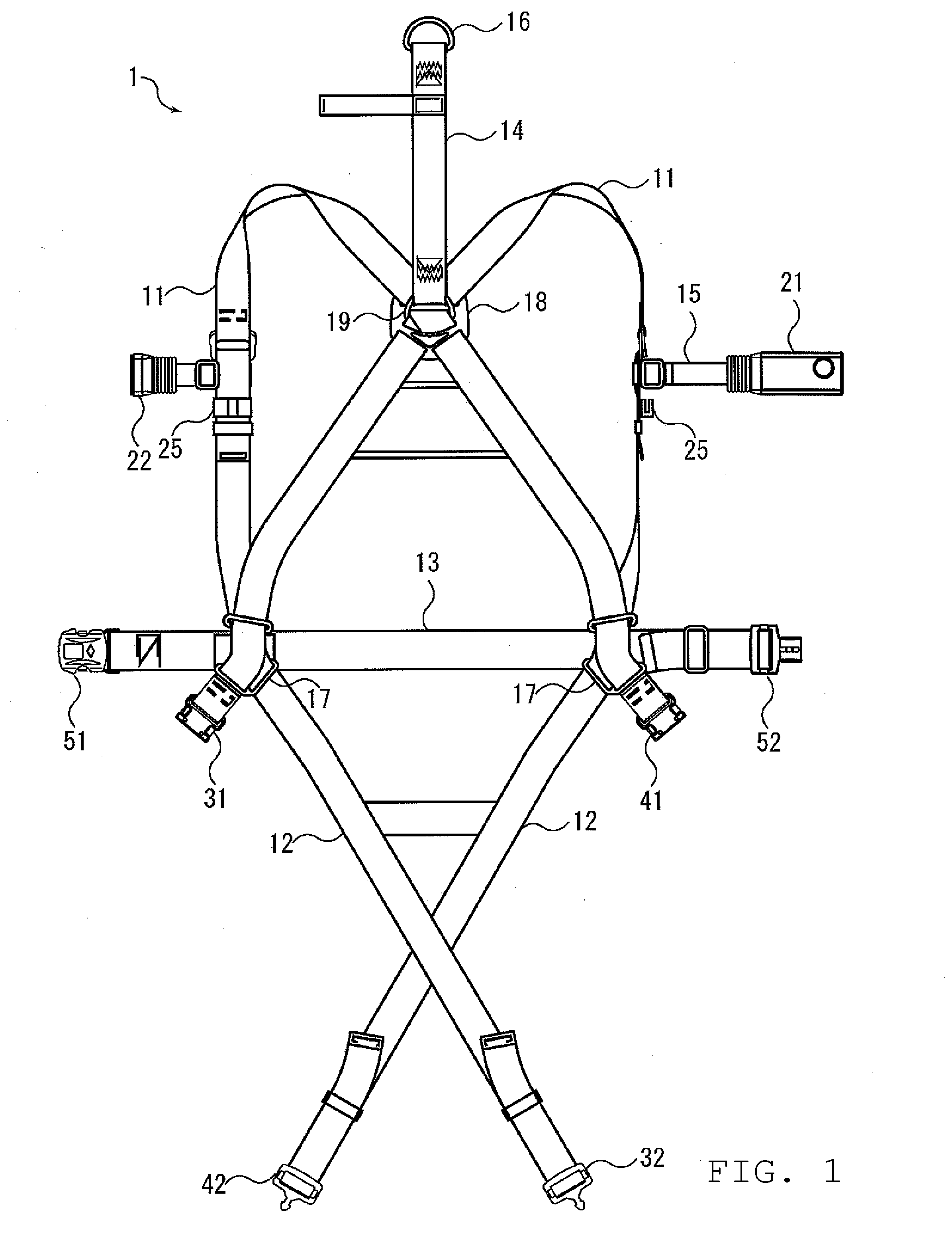
[0048]FIG. 1 shows an unworn configuration of a safety belt 1 in the first preferred embodiment of the present invention. The safety belt 1 is a full-body harness type and includes a pair of shoulder belts 11, 11, a pair of thigh belts 12, 12, and a waist belt 13.

[0049]The shoulder belts 11, 11, i.e., right and left belts are arranged to be worn around the upper body of a worker such that the shoulder belts 11, 11 cross each other on the back of the worker, go over the right and left shoulders to reach the chest. The shoulder belts 11, 11 further extend from the chest to the waist, and one ends of the shoulder belts 11, 11 are inserted into right and left connectors 17, 17 arranged on the right and left side of the waist, respectively. Below the connectors 17, 17, the shoulder belts 11, 11 continue to the thigh belts 12, 12.

[0050]Also, on the back of the body, the shoulder belts 11, 11 are arranged to extend from the intersec...

second preferred embodiment

[0104]The second preferred embodiment of the present invention is now described. In the following description, the same reference signs as those in the first preferred embodiment are used for the same or similar components as / to those in the first preferred embodiment, and the redundant description is omitted.

2-1. Structure of Safety Belt

[0105]FIG. 14 shows the appearance of a safety belt according to this preferred embodiment. As shown in FIG. 14, the safety belt of this preferred embodiment is a connecting member 2 in the form of a lanyard. The connecting member 2 includes a rope 70, a hook 24, and a carbine hook 71. The user who bought the connecting member 2 of this preferred embodiment uses it while attaching it to the user's body belt. Please note that the connecting member 2 can be attached to any of a full-body harness type and a waist-belt type. The connecting member 2 is used together with the control box 21 described in the first preferred embodiment. Thus, it is possible...

third preferred embodiment

[0131]Still another preferred embodiment of the present invention is now described. The same or similar structure and configuration as / to that described in the aforementioned preferred embodiments are labeled with the same reference signs and the redundant description is omitted.

3-1. Configuration of Connecting Member

[0132]A safety belt of this preferred embodiment is a connecting member 3 in the form of a lanyard. FIG. 20 shows the appearance of the connecting member 3 of this preferred embodiment. As shown in FIG. 20, the connecting member 3 includes a rope 30, a hook 34, and a carbine hook 35. The user who bought the connecting member 3 of this preferred embodiment uses it while attaching it to the user's body belt. As the body belt, both a full-body harness type and a waist-belt type can be used. The connecting member 3 is used together with the control box 21 of the first preferred embodiment. That is, it is possible to sell the connecting member 3 and the control box 21 which ...


PUM


Abstract

A safety belt includes a connecting member including a rope, an attaching portion connected to a first end of the rope and arranged to be attached to a body belt worn around a body of a worker, a hook connected to a second end of the rope, and a load detection portion arranged to detect whether or not a load is applied to the connecting member and to output a load detection signal. The safety belt also includes a control device that includes a receiver unit arranged to receive the load detection signal, a control unit arranged to determine a status of the worker or a status of the safety belt based on the load detection signal, and a notification unit arranged to provide a notification in accordance with control by the control unit corresponding to the determined status.

Description

BACKGROUND OF THE INVENTION[0001]1. Field of the Invention[0002]The present invention relates to a safety belt preferably used for a worker in high places, for example, and a system for checking a usage status of the safety belt.[0003]2. Description of the Related Art[0004]Workers in high places like construction sites are required to wear safety belts for the purpose of preventing a fall. A typical safety belt includes a body belt worn around the worker's body; a rope-like connecting member with one end connected to the body belt, called a safety tether or lanyard; and a hook connected to the other end of the connecting member. The worker wears the body belt around the body and attaches the hook to a lifeline, ladder or the like in the construction site to ensure safety while working.[0005]There are two known types of safety belts. The first type is a waist-belt type to be worn around the worker's waist and the second type is a full-body harness type which can hold the full body of...

Claims


Application Information

Patent Timeline
Patent Type & Authority Applications(United States)
IPC IPC(8): G08B1/08A62B35/00A62B35/04
CPCA62B35/0075A62B35/0025
Inventor MORINO, OSAMUKOZUKI, AKITOMOMURATA, MICHIHIRO
Owner FUJII DENKO CO LTD
Learn More