
Safety belt retractor with cutoff of its belt-webbing-sensitive and its vehicle-sensitive control system

a belt retractor and safety technology, applied in the field of self-locking belt retractors, to achieve the effect of facilitating the pre-mounting of the belt retractor according to the invention

Active Publication Date: 2011-04-21
AUTOLIV DEV AB
View PDF7 Cites 11 Cited by
  • Summary
  • Abstract
  • Description
  • Claims
  • Application Information

AI Technical Summary

Benefits of technology

[0009]In its basic idea, the invention provides that for the formation of inertia on of the control disc, an inertial mass is swivellably mounted thereon, and is deflectable into a blocking position for the control disc. Additionally, a locking lever for disabling a vehicle sensor is also mounted on the control disc. According to a switching process in a cutoff position of the locking lever, the locking lever cuts off the vehicle sensor and also secures the inertial mass in a disabling position which is different from the blocking position. Unlike the prior art, the mass moment of inertia of the control disc is produced by an inertial mass which is pivotably mounted on the control disc, whereby the vehicle sensor is cut off and the inertial mass is secured from potential movement by way of a single locking lever, and wherein the belt-webbing-sensitive control system is cut off at the same time. Accordingly, the invention also entails the advantage that only a single component and a single switching process are necessary in order to cut off (or disable) both control systems together. As the locking lever is likewise mounted on the control disc itself, all the components necessary for the cutoff are concentrated on the control disc, so that the structure of the belt retractor is simplified.
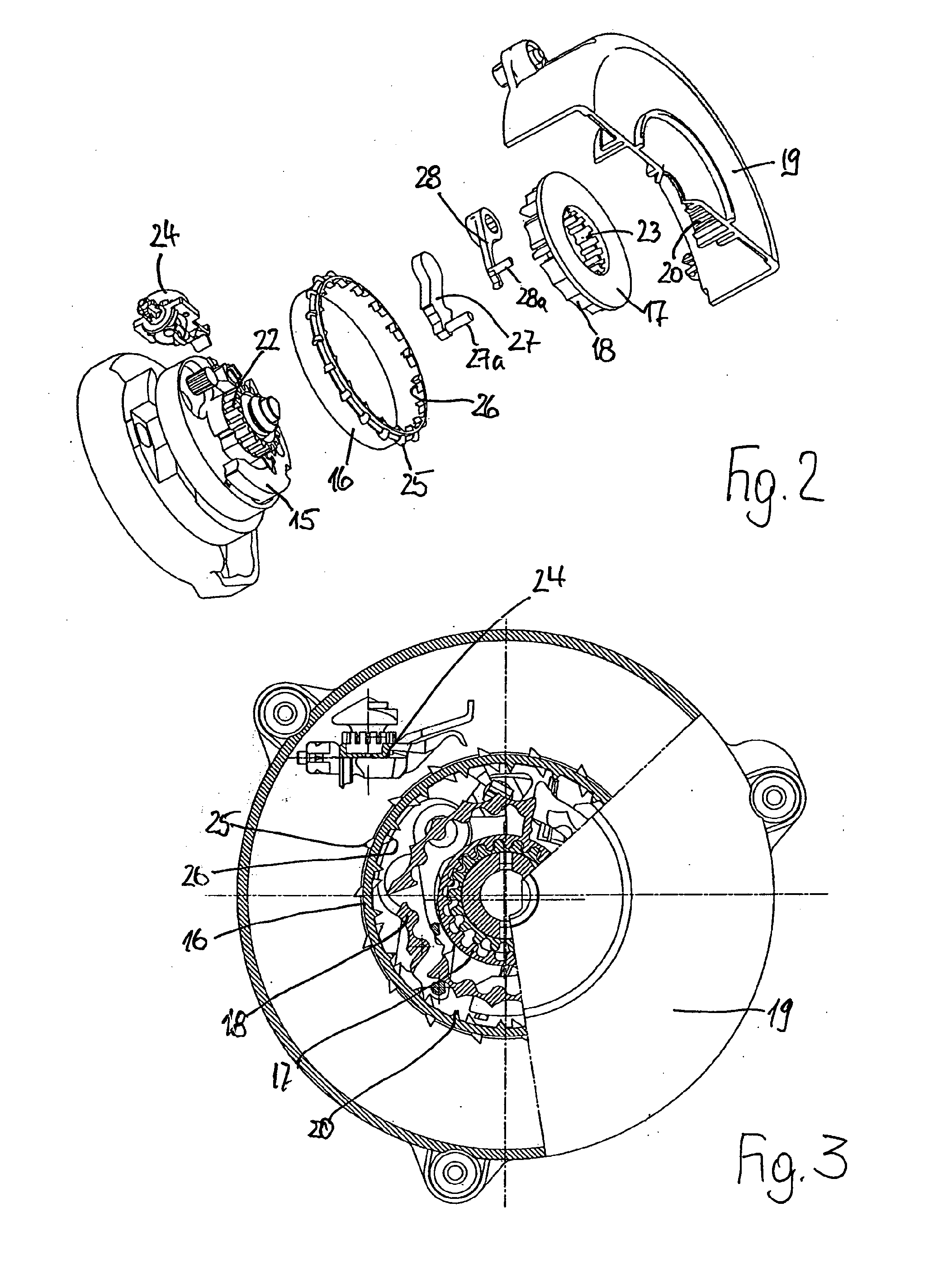
[0014]According to an exemplary embodiment of the present invention, insofar as the switching lever does not engage with the peripheral toothing of the housing cap during the ELR switching state, provision is made that the switching lever is secured with a spring arm on a structural part of the control disc, wherein in its radially deflected ALR switching position, the spring arm comes out of engagement with the structural part of the control disc. Owing to the spring engagement, which is thus set, incorrect controlling of the switching lever is avoided.
[0024]The circumstance can also occur that in the case of a very rapid belt webbing withdrawal, on reaching the ELR / ALR switchover point, the guide pin situated on the switching lever breaks off, so that a switching back to the ELR operation is not possible due to a faulty return of the switching lever on the inner cam of the strip. In order to nevertheless make possible a switching back in such a case, provision can be made that the locking lever and switching lever are arranged in different planes, staggered in the axial direction of the control disc, and the locking lever has an attachment extending into the movement plane of the switching lever and carrying the guide pin, wherein the attachment cooperates with the switching lever in at least one switching position of the locking lever. When the locking lever, on rolling up of the belt webbing such that the belt webbing is sufficiently wound, changes from the outer cam into the inner cam, the locking lever presses the switching lever back via its attachment, even in the absence of the guide pin in its abutment characterizing the ELR operation on the third cam on the periphery of the bearing ring. For structural reasons, provision can be made that for the production of the necessary motion clearance for the switching pin, the inertial mass extends in its axial height over both movement planes of the locking lever and switching lever, and has a cutout to receive the switching lever, wherein the cutout is arranged in the movement plane of the switching lever. As such, a space-saving compact construction of the components which are to be arranged on the control disc can be achieved.
[0028]The pre-mounting of the belt retractor according to the invention is then facilitated, insofar as an exemplary embodiment provides that the adapter piece carries the control disc on an encircling flange and thereby forms the pre-mounted assembly which is to be engaged with the housing cap, wherein the shaft extension can be fixedly inserted into the adapter piece which is secured on the housing cap.

Problems solved by technology

Secondly, the control disc includes an outer ring rotatable with respect to the platform.

Method used


Image

  • Safety belt retractor with cutoff of its belt-webbing-sensitive and its vehicle-sensitive control system
  • Safety belt retractor with cutoff of its belt-webbing-sensitive and its vehicle-sensitive control system
  • Safety belt retractor with cutoff of its belt-webbing-sensitive and its vehicle-sensitive control system

Examples


Embodiment Construction

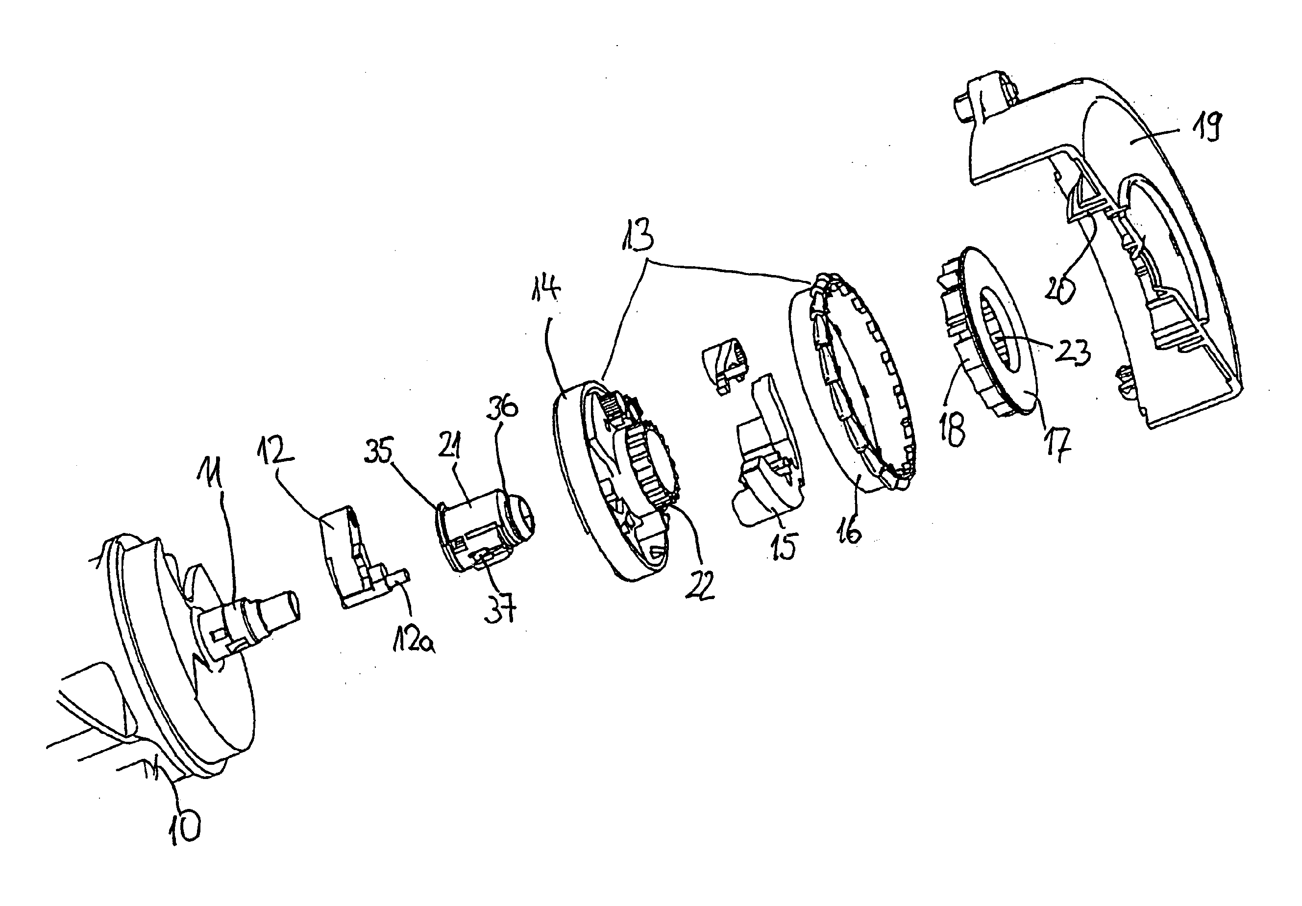
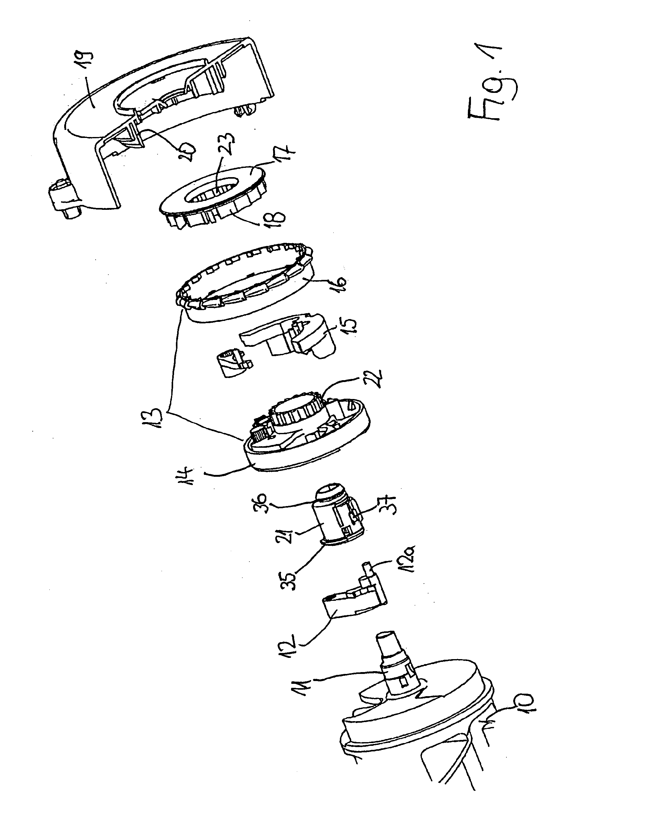
[0046]As can be seen firstly from FIGS. 1 and 2, a system side of a self-locking belt retractor is shown comprising a belt shaft 10 with a shaft extension 11 projecting therefrom along a shaft axis defined by the belt shaft 10, wherein the belt shaft 10 serves as mounting means and as drive means for the system parts connected to the belt shaft 10. A blocking catch 12 is mounted on the belt shaft 10 and is able to be swung out radially for engagement into a toothed blocking (not illustrated) fixed to the housing, wherein the blocking catch 12 has a guide pin 12a projecting in the shaft axis. The guide pin 12a engages into a link formed on a control disc 13, such that the control disc 13 rotates respectively together with the belt shaft 10. In the case of a response by a vehicle-sensitive and / or belt-webbing-sensitive control system which is to be described below, the control disc 13 is blocked from further rotary movement, so that relative rotation is produced between the stationary...


PUM


Abstract

A self-locking belt retractor for motor vehicles with a vehicle-sensitive and a belt-webbing-sensitive control system for the blocking arrangement of the belt retractor, is characterized in that for the formation of its inertia, an inertial mass is swivellably mounted on a control disk, wherein the inertial mass can be deflected into a blocking position for the control disc. Additionally, a locking lever mounted on the control disc is provided for the cutoff of a vehicle sensor, and by way of a switching process in its cutoff position, the locking lever cuts off the vehicle sensor and secures the inertial mass in a disabling position, the disabling position being different than the blocking position.

Description

CROSS REFERENCE TO RELATED APPLICATION[0001]This application claims priority to International Application No. PCT / EP2007 / 010303, filed Nov. 28, 2007, which is based on and claims priority to German Patent Application No. DE 10 2006 057 018.9, filed Dec. 2, 2006.FIELD OF THE INVENTION[0002]The invention relates to a self-locking belt retractor for motor vehicles, with a vehicle-sensitive and a belt-webbing-sensitive control system for a locking device of the belt retractor. The belt retractor includes a toothed wheel able to be guided into a toothing fixed to the housing of the belt retractor, wherein the control system comprises a control disc rotating with the belt shaft. The control disc is coupled to the toothed wheel and in order to form its inertia, the control disc is constructed with an inertial mass swivellably mounted thereon for the formation of the belt-webbing-sensitive control. The control disc includes an outer toothing for engaging a sensor lever arranged on a vehicle...

Claims


Application Information

Patent Timeline
IPC IPC(8): B60R22/41B60R22/405
CPCB60R22/41B60R22/405
Inventor GUILLEM, ARANDA
Owner AUTOLIV DEV AB
Learn More