
Ultrasonic device having memory capabilities

a technology of ultrasonic dental tools and memory, which is applied in the direction of instruments, dental surgery, cleaning using liquids, etc., can solve the problems of premature wear and replacement of ultrasonic dental tips, fatigue of dental tips themselves, and wear and tear of dental inserts over tim

Active Publication Date: 2011-04-14
INTERMED
View PDF10 Cites 48 Cited by
  • Summary
  • Abstract
  • Description
  • Claims
  • Application Information

AI Technical Summary

Benefits of technology

[0013]Additionally, it is also possible that the dental tool or base station may interface with elements in the dental tip. For example, if a tip were identified by the base station and the tip were operated outside of its recommended operating parameters, then the base station could send an electronic signal to the tip to overload an electronic device. The failure of the small electronic device would provide a parameter which would then be easy for a manufacturer to evaluate upon receipt of the returned tip. Thus in this example, a manufacturer would be able to easily obtain data about the usage of a particular dental tip to support warranty claims.
[0016]Specifically, the base station could continually transmit an electrical characteristic to the safety protection or monitoring device, however once the amplitude level of the dental tip was increased beyond the rated usage, the electrical characteristic from the base station would overload the safety protection or monitoring device. Upon review of the dental tip, the manufacturer would be able to determine that the tip was used under conditions not recommended since the safety protection device had failed. This could be determined as easily as measuring the resistance across the safety protection device, and would allow the manufacturer to either void or honor the warranty of the dental tip.

Problems solved by technology

The dental insert can wear over time and may need to be replaced.
Depending on the specific use for the ultrasonic device and the specific dental attachment used, the power amplitude of the ultrasonic device may need to be changed—improper setting of the power amplitude may prematurely wear out the ultrasonic dental tip.
However, during general use, the dental tips themselves may become fatigued.
The dental tips for these devices may wear over time, regardless of how the dental tip has been used.
Nonetheless, due to the relatively smaller size and configuration of these devices compared to magnetorestrictive devices, it has not been possible to monitor the characteristics of these devices effectively, as with magnetorestrictive devices.
Consequently, determining specifically how and why a dental tip failed is not always possible.

Method used


Image

  • Ultrasonic device having memory capabilities
  • Ultrasonic device having memory capabilities
  • Ultrasonic device having memory capabilities

Examples


Embodiment Construction

[0026]Although the disclosure hereof is detailed and exact to enable those skilled in the art to practice the invention, the physical embodiments herein disclosed merely exemplify the invention which may be embodied in other specific structures. While the preferred embodiment has been described, the details may be changed without departing from the invention, which is defined by the claims.

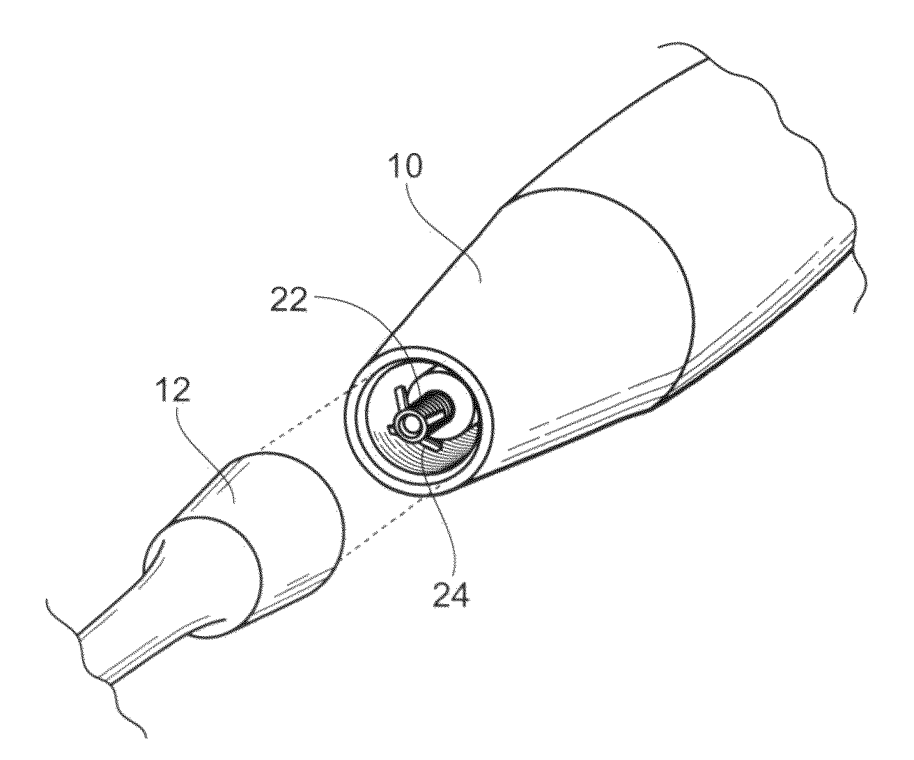
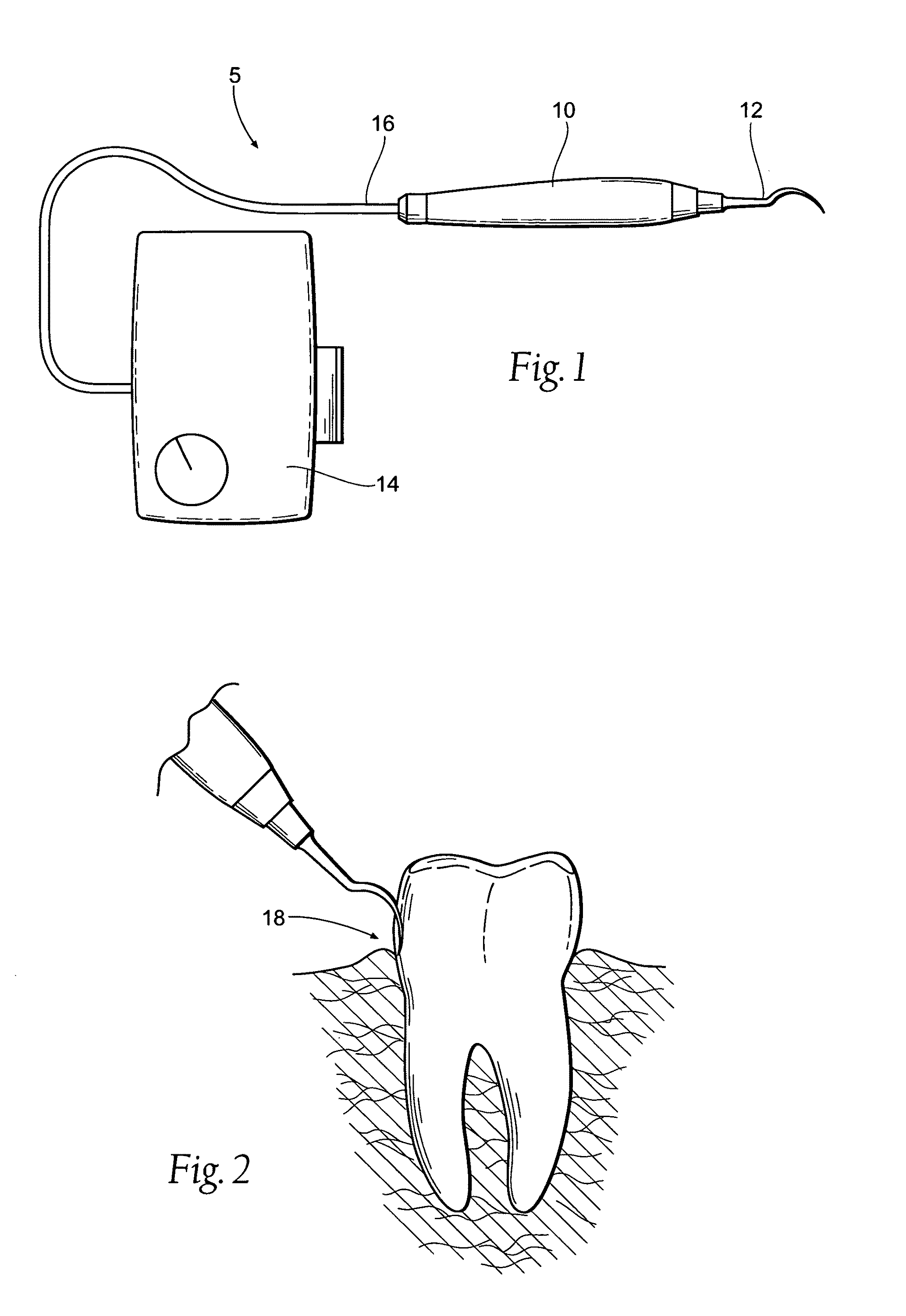
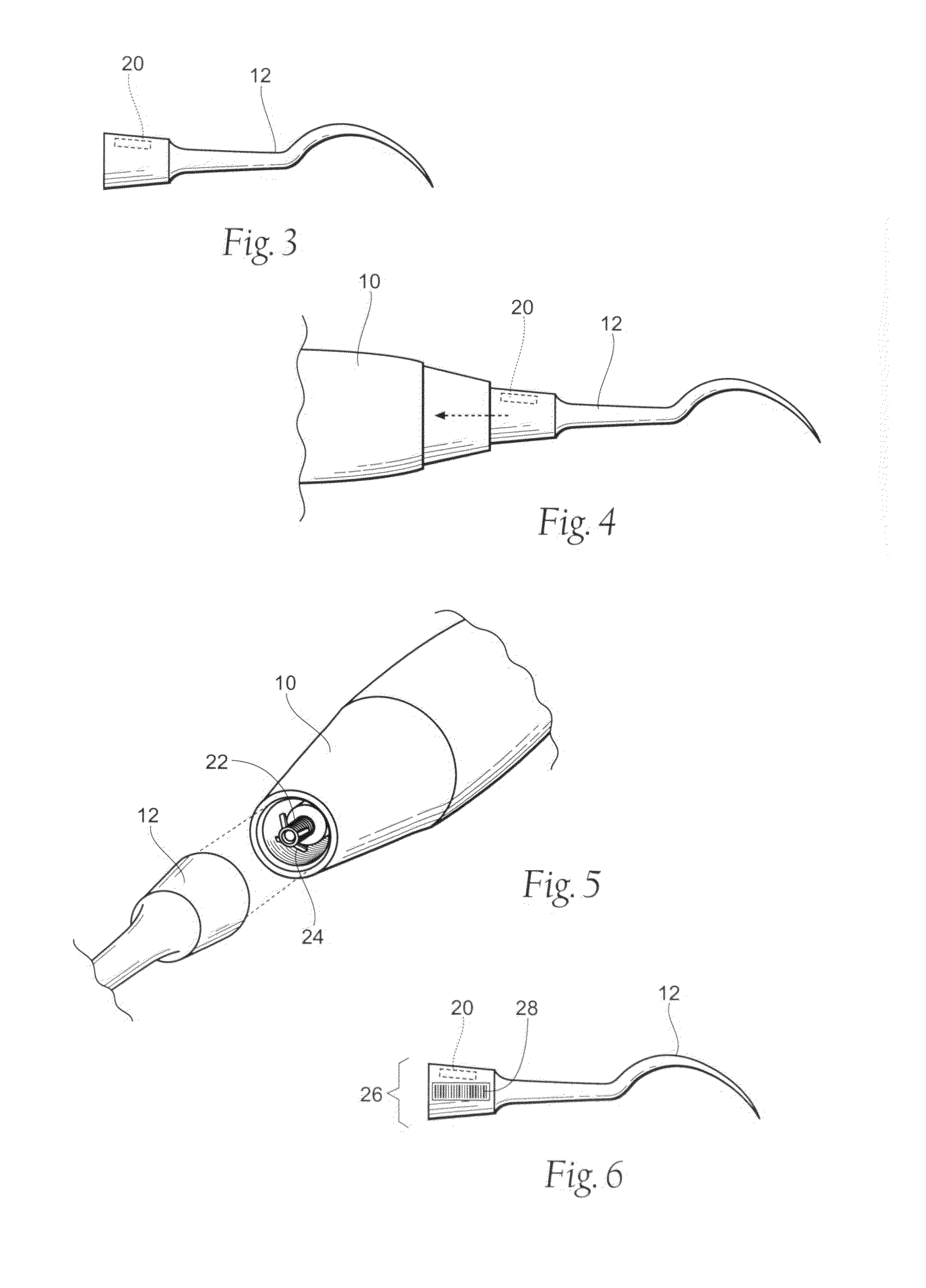
[0027]FIG. 1 depicts a dental assembly 5 that generally comprises a dental handpiece 10 and a dental needle or tip 12 connected to the handpiece 10. The handpiece 10 is connected to a base station 14 by way of a power cord 16. It is also possible that the handpiece 10 could be connected to the base station via a wireless arrangement. The base station 14 generally comprises various controls and control functions for the handpiece 10 and the dental tip 12, such as providing a power source, providing temperature controls, providing controls for the speed and frequency for the operation of the handpie...


PUM


Abstract

A dental device capable of monitoring at least one characteristic of the dental device. The characteristics are monitored by the use of microchips; radio frequency identification devices (RFID), bar codes, resistors, diodes, semiconductors, and magnetic strips.

Description

RELATED APPLICATIONS[0001]This application claims the benefit U.S. Provisional Patent Application Ser. No. 61 / 214,961, filed 30 Apr. 2009.BACKGROUND OF THE INVENTION[0002]The present invention relates to ultrasonic dental tools, and, more specifically, to ultrasonic dental tools that incorporate devices that can record and store operational information of the ultrasonic dental tool.[0003]Ultrasonic devices are commonly used in dental procedures, such as root canal procedures, scaling and cleaning procedures, and other various dental procedures. These devices generally comprise a handpiece connected to a dental tip or other similar attachment. The handpiece will generally be connected to a power source and / or housing, and one or more fluid sources. There are two distinct types of ultrasonic devices, magnetorestrictive and piezoelectric ultrasonic devices.[0004]Magnetorestrictive devices are designed to hold a dental insert within the body of the device. The dental insert is placed wi...

Claims


Application Information

Patent Timeline
Patent Type & Authority Applications(United States)
IPC IPC(8): A61C17/20G06Q10/00
CPCG06Q30/012A61C3/03A61C17/20
Inventor POND, GARY J.
Owner INTERMED
Learn More