
De-noising method and related apparatus for image sensor

a technology of image sensor and noise reduction, applied in the field of image processing, can solve the problems of principal sources of noise in digital images, no image is absolutely perfect, and the packaging is very complex, so as to reduce noise, blur the edges and other image details, and remove as much noise

Inactive Publication Date: 2011-04-14
HIMAX IMAGING LIMITED
View PDF11 Cites 12 Cited by
  • Summary
  • Abstract
  • Description
  • Claims
  • Application Information

AI Technical Summary

Benefits of technology

[0007]It is therefore one of the objectives of the present invention to provide a de-noising method and related apparatus utilizing a specific noise threshold value for an image sensor, to remove as much noise as possible while blurring the edges and other image details as little as possible.

Problems solved by technology

This would be prohibitive due to the high cost and would also cause the packaging to be very complex.
No images are absolutely perfect no matter how good the camera, since images are interfered with by the presence of noise.
The principal sources of noise in digital images arise during image acquisition, digitization, and / or transmission.
For instance, when acquiring images with a Charge-Coupled Device (CCD) sensor or a CMOS image sensor, luminosity and sensor temperature are major factors affecting the amount of noise in the generated images.
For example, any noise in images will result in serious errors due to many applications being based on operands drawn out from applications for calculating images.

Method used


Image

  • De-noising method and related apparatus for image sensor
  • De-noising method and related apparatus for image sensor
  • De-noising method and related apparatus for image sensor

Examples


Embodiment Construction

[0017]Certain terms are used throughout the description and following claims to refer to particular components. As one skilled in the art will appreciate, manufacturers may refer to a component by different names. This document does not intend to distinguish between components that differ in name but not function. In the following description and in the claims, the terms “include” and “comprise” are used in an open-ended fashion, and thus should be interpreted to mean “include, but not limited to . . . ”.

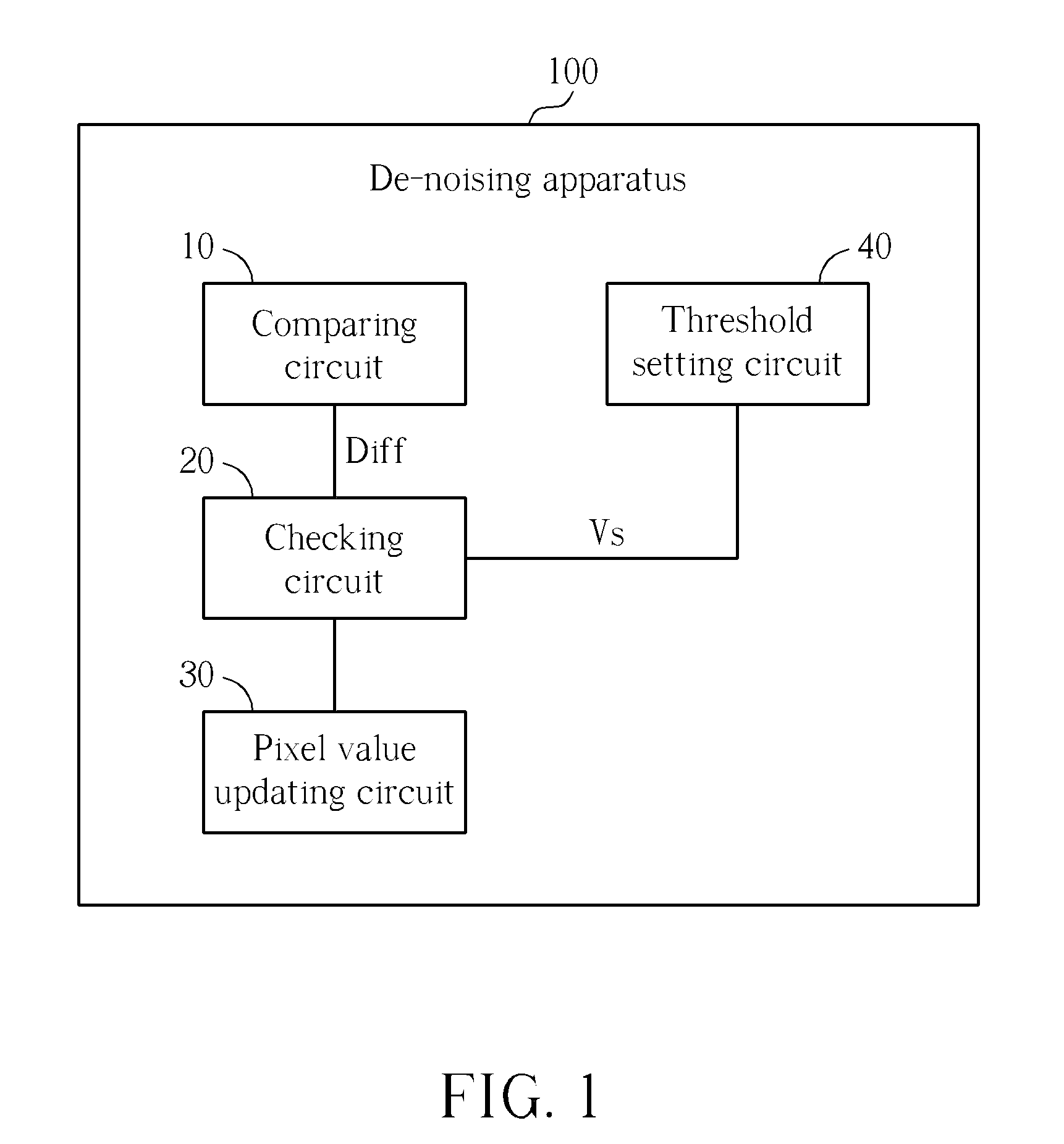
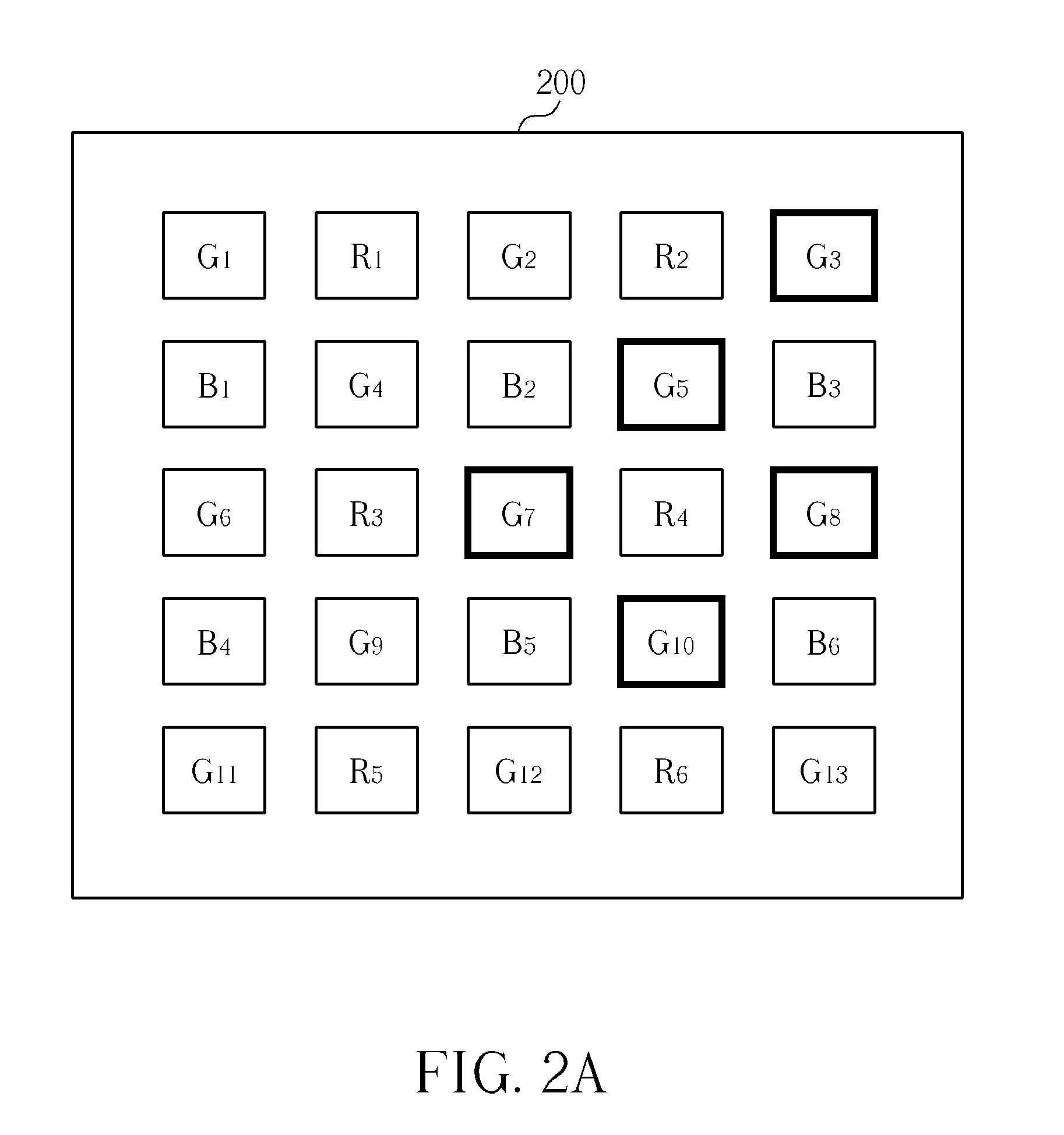
[0018]Please refer to FIG. 1. FIG. 1 is a diagram illustrating a de-noising apparatus 100 for an image sensor according to an exemplary embodiment of the present invention. The de-noising apparatus 100 utilizes a specific noise threshold value Vs for the image sensor. The image sensor includes a specific color filter array and a pixel array. Each pixel corresponds to one color filter, and thus corresponds to one of a plurality of color components. For the purpose of explanatory conv...


PUM


Abstract

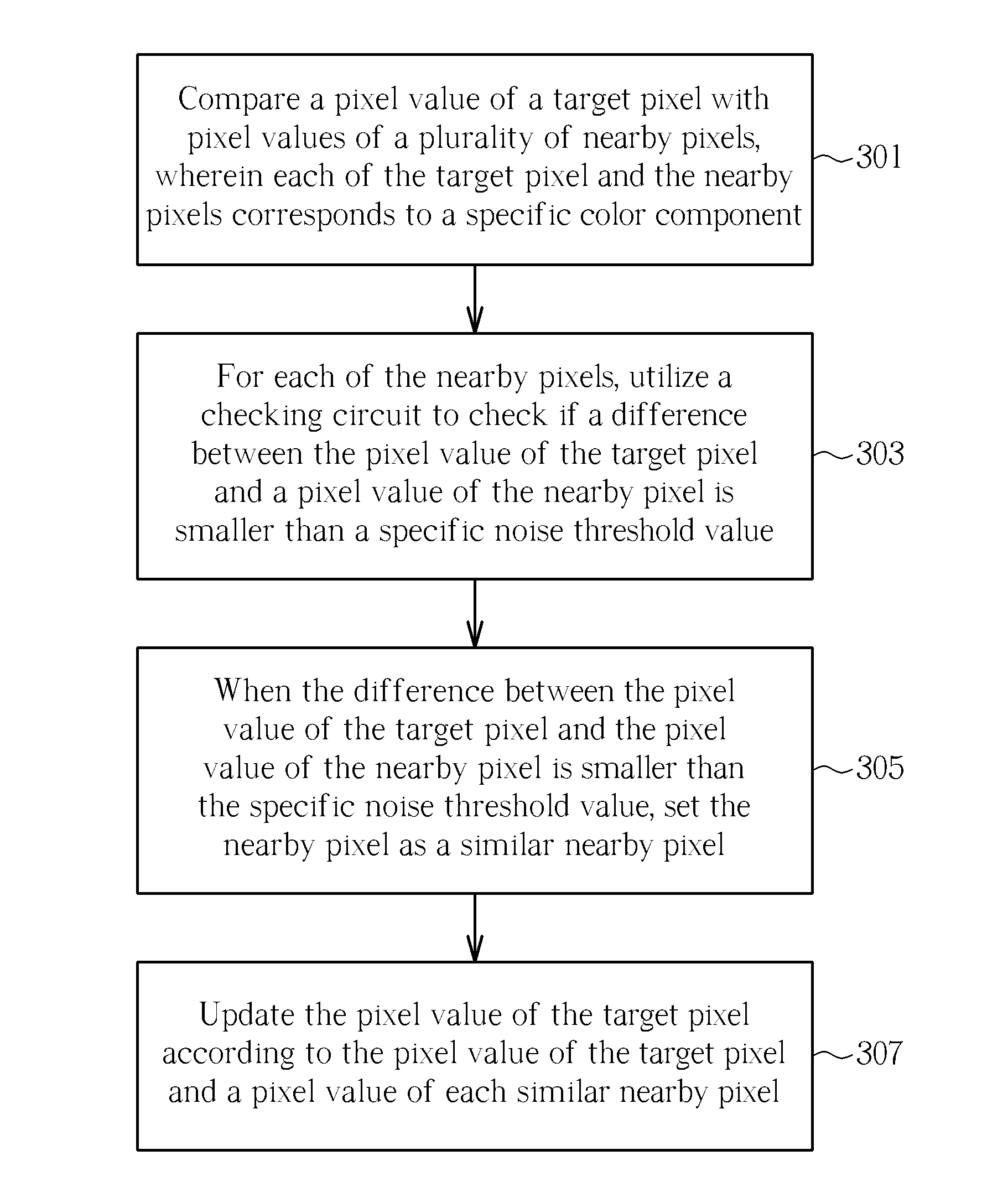
A de-noising method includes: comparing a pixel value of a target pixel with pixel values of a plurality of nearby pixels, wherein each of the target pixel and the nearby pixels corresponds to a specific color component; for each nearby pixel of the nearby pixels, checking if a difference between the pixel value of the target pixel and a pixel value of a nearby pixel of the nearby pixels is smaller than a specific noise threshold value, and when the difference between the pixel value of the target pixel and the pixel value of the nearby pixel is smaller than the specific noise threshold value, setting the nearby pixel as a similar nearby pixel; and updating the pixel value of the target pixel according to the pixel value of the target pixel and a pixel value of each similar nearby pixel.

Description

BACKGROUND OF THE INVENTION[0001]1. Field of the Invention[0002]The present invention relates to image processing, and more particularly, to a de-noising method and related apparatus utilizing a specific noise threshold value for an image sensor.[0003]2. Description of the Prior Art[0004]In an imaging system, three components of color information must be captured simultaneously to precisely present an image. To create an analogous digital imaging system that simultaneously captures all three components of the color information requires three individual imaging detectors. This would be prohibitive due to the high cost and would also cause the packaging to be very complex. To keep the size and cost of a digital video imaging system to a minimum, an image sensor array of the system must also be kept to a small size. Therefore, the number of color samples must be kept low. An alternative approach is to have each detector of the imaging system gather data for a single color to create a s...

Claims


Application Information

Patent Timeline
Patent Type & Authority Applications(United States)
IPC IPC(8): G06K9/40H04N5/217
CPCH04N5/3572H04N2209/045H04N9/045H04N25/611H04N25/134
Inventor SHI, MIAOHONGMITTRA, AMIT
Owner HIMAX IMAGING LIMITED
Learn More