
Weld seam tracking system using phased array ultrasonic devices

a phased array and ultrasonic technology, applied in the direction of manufacturing tools, instruments, specific gravity measurement, etc., can solve the problems of preventing the full automation of presenting quite a degree of difficulties, and unable to fully automate the welding and weld inspection system, etc., and achieve the effect of high cost of manual tracking

Active Publication Date: 2011-04-14
OLYMPUS AMERICA
View PDF4 Cites 47 Cited by
  • Summary
  • Abstract
  • Description
  • Claims
  • Application Information

AI Technical Summary

Benefits of technology

[0011]The invention disclosed herein aims to solve the problems related to weld seam tracking for positioning NDT / NDI devices to perform weld seam inspections, while avoiding the existing weld seam tracking techniques having the aforementioned drawbacks, such as inefficiency and high cost of manual tracking or using extra sensor / tracking devices external to the NDT / NDI inspection devices.
[0013]Accordingly, it is a general object of the present disclosure to provide a weld seam tracking device that directly uses NDT / NDI sensor(s) in conjunction with an NDT / NDI operation. Processing of the weld seam tracking algorithm can be easily integrated to or combined with the existing data processing element of existing NDT / NDI inspection devices.
[0015]It is further an object of the present disclosure to make use of the advantages of PA probes which provide a wider scan area than that of single or dual element probes, so that the scan area can cover the whole width of a weld seam and its vicinity. This is significant because it allows weld seam tracking and inspection to be done smoothly in one move along the direction of weld seam. It inherently eliminates the need to move the sensor across a large or the whole surface of the test object to locate the weld seam.
[0016]It is further an object of the present disclosure to perform weld seam tracking in conjunction of weld inspection, eliminating the need for any extra sensors, such as laser or infra-red sensor, and the need of any extra data processing capacity related to the extra sensors. Inherently, the novel approach as disclosed reduces material and operational cost, and increases operational efficiency.

Problems solved by technology

For some weld inspection applications, one of the challenges lies in how to efficiently and / or automatically track the position of the welds and therefore guide the inspection probes that are placed in immediate proximity of the welds.
One of the drawbacks of the manual tracking method described above is that it prevents the full automation of the welding and weld inspection system because the operator must be present to monitor and adjust the weld seam location as required.
A limitation presented by this method is that it requires a visible marked line along the pipe to guide the PA probe to follow the weld seam.
Painting a visible line (called also the pilot line) at a given distance from the weld seam presents quite some degree of difficulties under industrial operation conditions.
In order to be precise, the pilot line has to be painted near the welding process location where the temperature is hot, consequently causing the marked line to lack paint or be partially masked.
If the contrast is poor, the device could lose the weld position.
Additional disadvantages of the Metavision device also include the use of a laser sensor and the need for two separate sets of sensors and associated hardware / software for weld seam tracking and inspection tasks, which leads to undesirable higher system investment.
The Girndt patent application addresses the weld seam tracking problem by employing an ultrasonic sensor to track the weld seam using two sets of sensors—one for tracking and the other for inspecting the weld seam, which presents increased material and operational costs.
Girndt also fails to mention the usage of phased array ultrasonic system, which prevents obtaining the capability to cover a wider stripe of scanning area along weld seam and its vicinity.
Furthermore, Girndt presents the limitation of requiring the scanning of the whole external pipe surface to obtain the weld seam position, which is extremely inefficient compared to scanning only the weld seam and the bordering region.

Method used


Image

  • Weld seam tracking system using phased array ultrasonic devices
  • Weld seam tracking system using phased array ultrasonic devices
  • Weld seam tracking system using phased array ultrasonic devices

Examples


Embodiment Construction

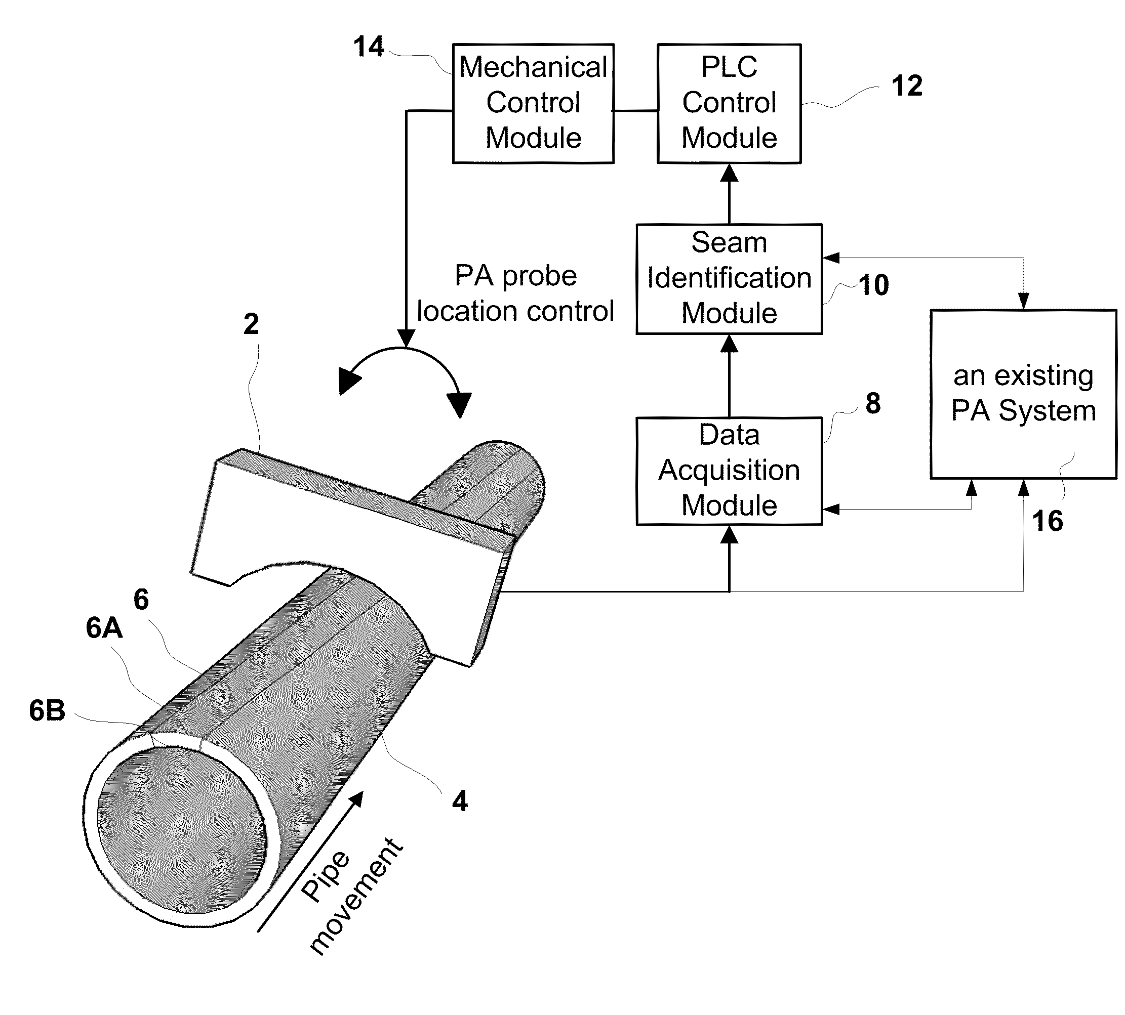
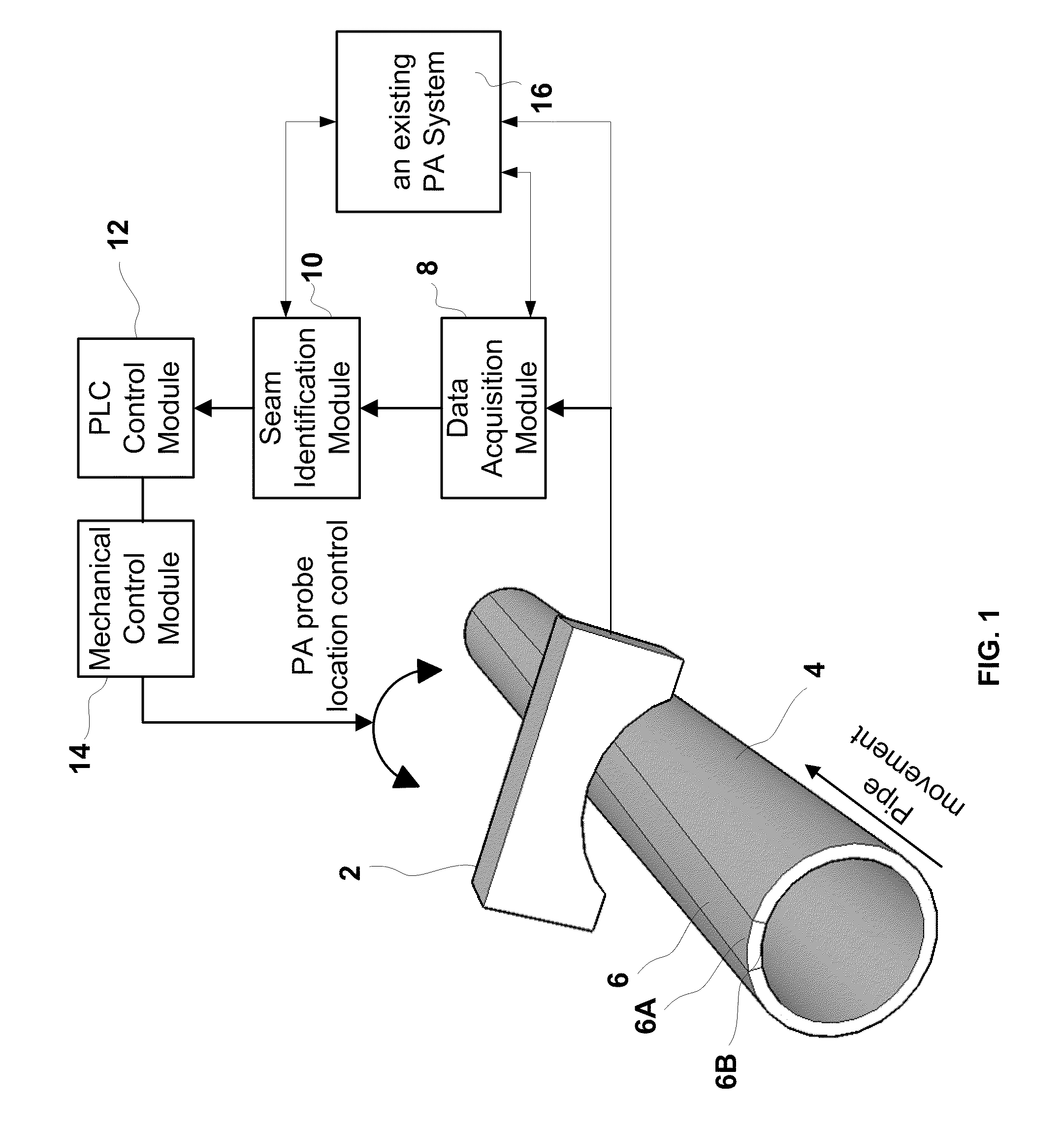
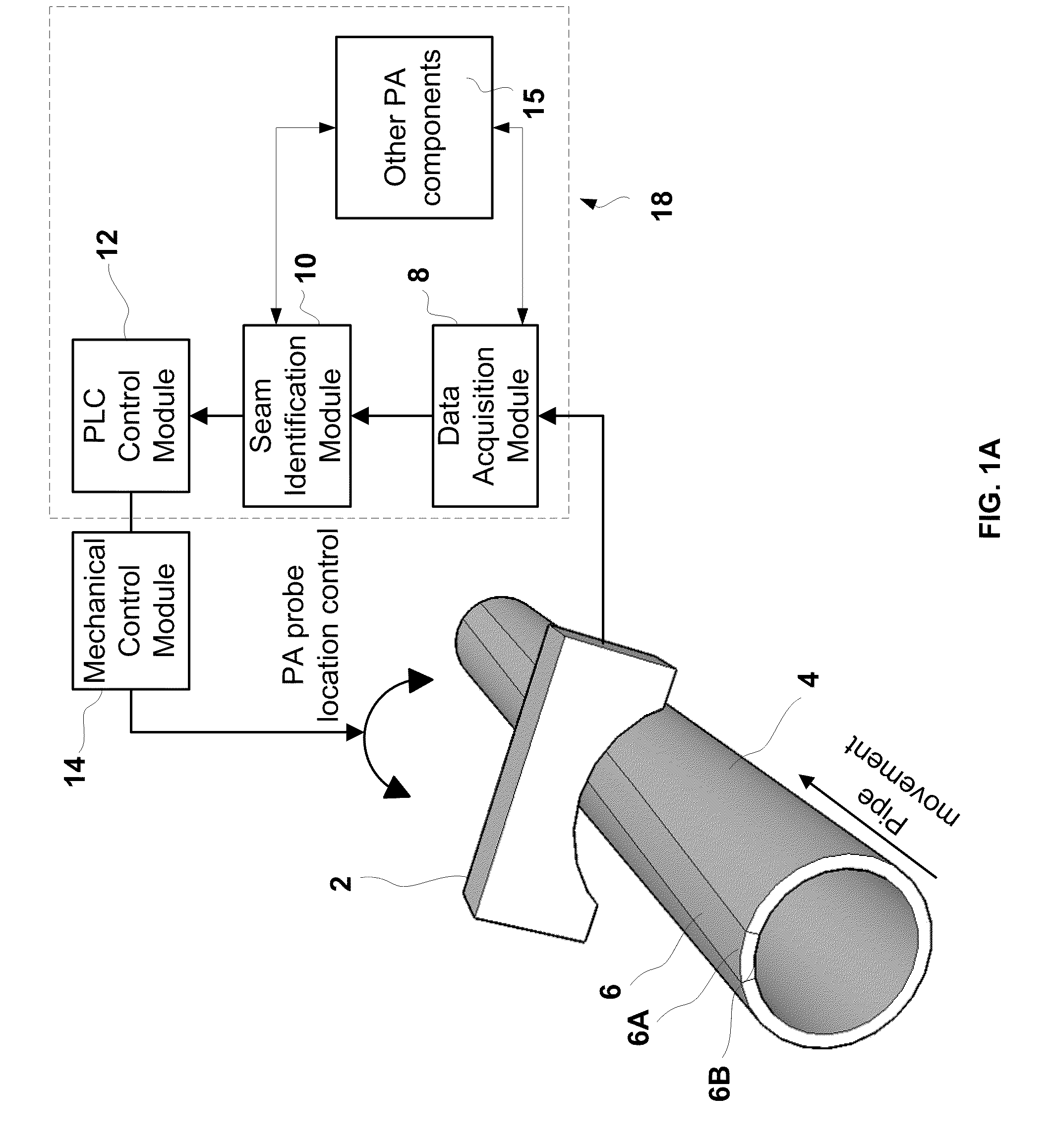
[0029]Referring to FIG. 1, the presently disclosed weld seam tracking device using a phased array system is comprised of a PA probe 2; a data acquisition module 8, a weld seam identification module 10 and a process logic control (PLC) control module 12 and a mechanical control module 14.

[0030]Using a conventional welding system production procedure as an example, pipe 4 is formed by being passed through a welding machine (not shown) to weld the two opposite edges of a bent rectangular metal sheet in order to form weld seam 6. Then, outer connecting surface 6A and inner connecting surface 6B of weld seam 6 are trimmed by the welding machine as the pipe moves away from the welding machine toward PA probe 2, creating a zone of thickness variation. During the process, the weld seam 6 on each pipe 4 may wander circumferentially on the transport mechanism (not shown) while the pipe is leaving the welding machine.

[0031]The presently disclosed weld seam and / or trimmed zone tracking device p...


PUM

PropertyMeasurementUnit
axial movementaaaaaaaaaa
lengthaaaaaaaaaa
ultrasonic inspectionaaaaaaaaaa

Abstract

A weld seam tracking device for tracking weld seams on pipes or the like uses NDT / NDI sensor(s) in conjunction with an NDT / NDI operation, such as an ultrasonic phased array (PA) inspection. Processing of the weld seam tracking data is integrated or combined with the existing data processing element of the existing NDT / NDI inspection devices. Wide scanning areas of phased array probes allow weld seam tracking and inspection to be performed using a single set of probe and data processing elements to achieve both fault scanning and seam tracking with a single run of the PA scan.

Description

FIELD OF THE INVENTION[0001]The present invention relates to non-destructive testing and inspection systems (NDT / NDI) and more particularly to an automatic weld seam tracking system using phased array (PA) devices in conjunction with NDT / NDI inspection operations.BACKGROUND OF THE INVENTION[0002]Welding is a long practiced process for joining separate metal objects together for the purpose of building support structures and producing pipes, vessles and other products. There are many types of welding techniques including gas welding, electric arc welding and electric resistance welding (ERW). A common characteristic of welded objects is the difference in thickness between the welded and non-welded regions.[0003]Inspection of weld integrity has long been recognized as crucially important because it enables the detection of cracking, porosity, incomplete penetration, inclusions, lack of sidewall fusion, and other defects that can compromise weld strength. Many existing NDT / NDI products...

Claims


Application Information

Patent Timeline
Patent Type & Authority Applications(United States)
IPC IPC(8): G01N29/04
CPCG01N29/0645G01N29/07G01N2291/2675G01N29/27G01N2291/106G01N29/262
Inventor IMBERT, CHRISTOPHE CLAUDEZHANG, JINCHI
Owner OLYMPUS AMERICA
Learn More