
Pixel shader output map

a shader and output map technology, applied in the field ofgraphics processing, can solve the problems of wasting storage resources and bandwidth, and involving a substantial amount of central processing unit (cpu) overhead, and achieve the effect of saving bandwidth

Active Publication Date: 2011-04-07
NVIDIA CORP
View PDF13 Cites 17 Cited by
  • Summary
  • Abstract
  • Description
  • Claims
  • Application Information

AI Technical Summary

Benefits of technology

[0008]A system and method of storing only the enabled components for each enabled vector and writing only enabled components to one or more specified render targets. A shader program header (SPH) file provides per-component mask bits for each render target. Each enabled mask bit indicates that the pixel shader generates the corresponding component as an output to the raster operations unit. In the hardware, the per-component mask bits are combined with the applications programming interface (API)-level per-component write masks to determine the components that are updated by the shader program. The combined mask is used as the write enable bits for components in one or more render targets. One advantage of the combined mask is that the components that are not updated are not forwarded from the pixel shader to the raster operations unit (ROP), thereby saving bandwidth between those processing units.

Problems solved by technology

Conventional pixel shaders store and output all of the multiple components for each enabled vector, potentially wasting storage resources and bandwidth when one or more of the components are disabled for a vector.
Additionally, disabled components that are output should not be written to a render target since the data for the component is undetermined.
However, such an approach involves a substantial amount of central processing unit (CPU) overhead.

Method used


Image

  • Pixel shader output map
  • Pixel shader output map
  • Pixel shader output map

Examples


Embodiment Construction

[0026]In the following description, numerous specific details are set forth to provide a more thorough understanding of the present invention. However, it will be apparent to one of skill in the art that the present invention may be practiced without one or more of these specific details. In other instances, well-known features have not been described in order to avoid obscuring the present invention.

System Overview

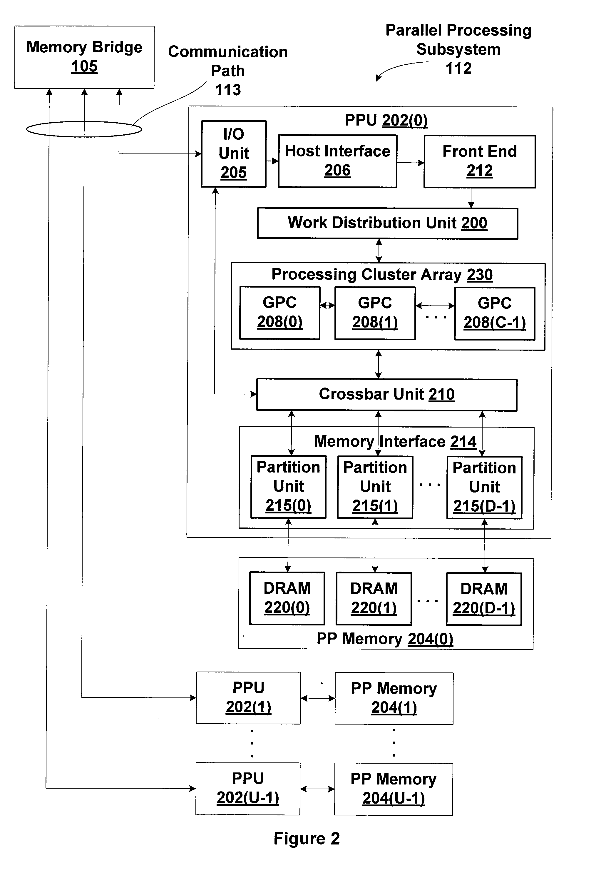
[0027]FIG. 1 is a block diagram illustrating a computer system 100 configured to implement one or more aspects of the present invention. Computer system 100 includes a central processing unit (CPU) 102 and a system memory 104 communicating via an interconnection path that may include a memory bridge 105. Memory bridge 105, which may be, e.g., a Northbridge chip, is connected via a bus or other communication path 106 (e.g., a HyperTransport link) to an I / O (input / output) bridge 107. I / O bridge 107, which may be, e.g., a Southbridge chip, receives user input from one or mor...


PUM


Abstract

One embodiment of the present invention sets forth a technique for storing only the enabled components for each enabled vector and writing only enabled components to one or more specified render targets. A shader program header (SPH) file provides per-component mask bits for each render target. Each enabled mask bit indicates that the pixel shader generates the corresponding component as an output to the raster operations unit. In the hardware, the per-component mask bits are combined with the applications programming interface (API)-level per-component write masks to determine the components that are updated by the shader program. The combined mask is used as the write enable bits for components in one or more render targets. One advantage of the combined mask is that the components that are not updated are not forwarded from the pixel shader to the ROP, thereby saving bandwidth between those processing units.

Description

CROSS-REFERENCE TO RELATED APPLICATIONS[0001]This application claims priority benefit to United States provisional patent application titled, “Pixel Shader Output Map,” filed on Oct. 7, 2009 and having Ser. No. 61 / 249,516 (Attorney Docket Number NVDA / SC-09-0298-US0).BACKGROUND OF THE INVENTION[0002]1. Field of the Invention[0003]Embodiments of the invention relate generally to graphics processing, and more specifically to selecting and transmitting components for output by a pixel shader.[0004]2. Description of the Related Art[0005]Prior art pixel shaders in three-dimensional (3D) graphics application programming interfaces (APIs) store and output component vectors of multiple components to a raster operations unit for blending operations and storage in a frame buffer. Vectors may be enabled or disabled for output to each render target (frame buffer) and one or more of the components in each vector may be individually disabled. Conventional pixel shaders store and output all of the ...

Claims


Application Information

Patent Timeline
IPC IPC(8): G06T15/80
CPCG06T15/005G09G5/363G09G5/393
Inventor DULUK, JR., JEROME F.HALL, JESSE DAVIDBROWN, PATRICK R.STADLER, MARK DENNIS
Owner NVIDIA CORP
Learn More