Rotary impingement cleaning apparatus for sanitary environments

Inactive Publication Date: 2011-04-07
ALFA LAVAL ASHBROOK SIMON HARTELY INC
View PDF5 Cites 13 Cited by
  • Summary
  • Abstract
  • Description
  • Claims
  • Application Information

AI Technical Summary

Benefits of technology

[0008]The invention rotary impingement cleaning apparatus described herein has a minimum of moving parts to encourage drainage of the cleaning liquid and to simplify inspection and service. The cleaning apparatus does not use the customary internal worm or planetary gear train drive. A pressurized liquid is connected to a housing inlet cap in a manner to pass through a stator. The stator diverts the flow path from axial to angular to form a vortex within the housing. The swirling liquid drives a rotator stem or a rotor. The rotating stem or rotor causes an elbow to rotate. A pair of bevel gears are mounted between the housing and a nozzle housing to cause a pair of nozzles to rotate around the h

Problems solved by technology

Food, cosmetic and pharmacologic ingredients are particularly susceptible to microbial contamination.
Spray balls have the advantage of not having internal moving parts, i.e. requiring little maintenance effort, but having the disadvantage of not being very effective for cleaning the interior walls of a tank.
However, conventional rotary impingement cleaning apparatus do not conform to the 3-A Standard.
A conventional rotary impingement cleaning apparatus typically has a complex internal mechanism, including either a worm gear transmission or a multiple stage planetary gear train, making self draining or self flushing of liquid and other 3-A Standard requirements unattainable.

Method used


Image

  • Rotary impingement cleaning apparatus for sanitary environments
  • Rotary impingement cleaning apparatus for sanitary environments
  • Rotary impingement cleaning apparatus for sanitary environments

Examples


Embodiment Construction

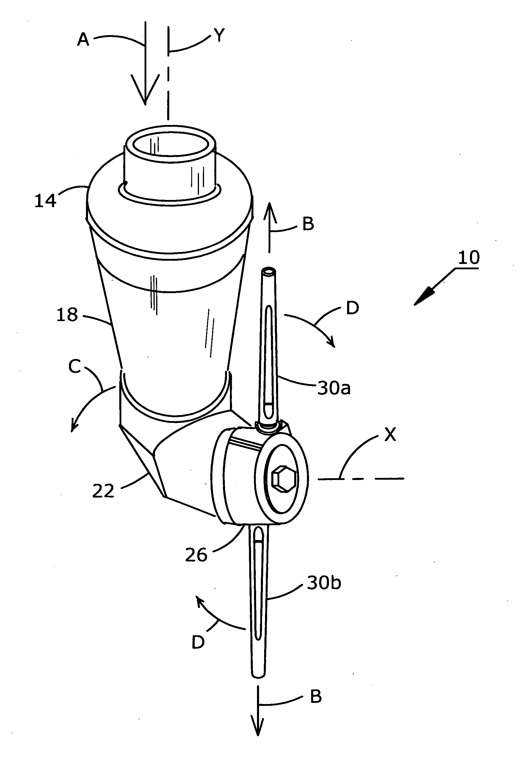
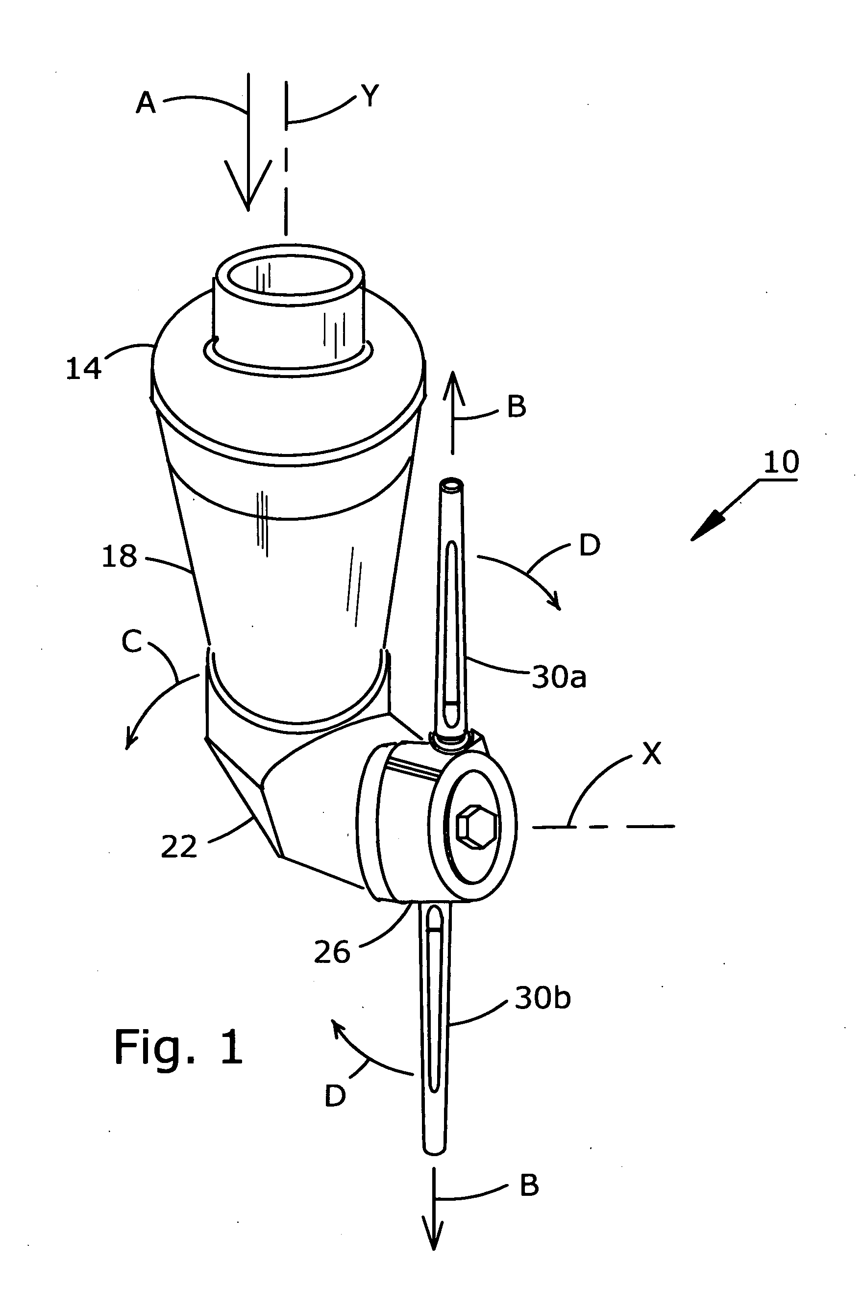
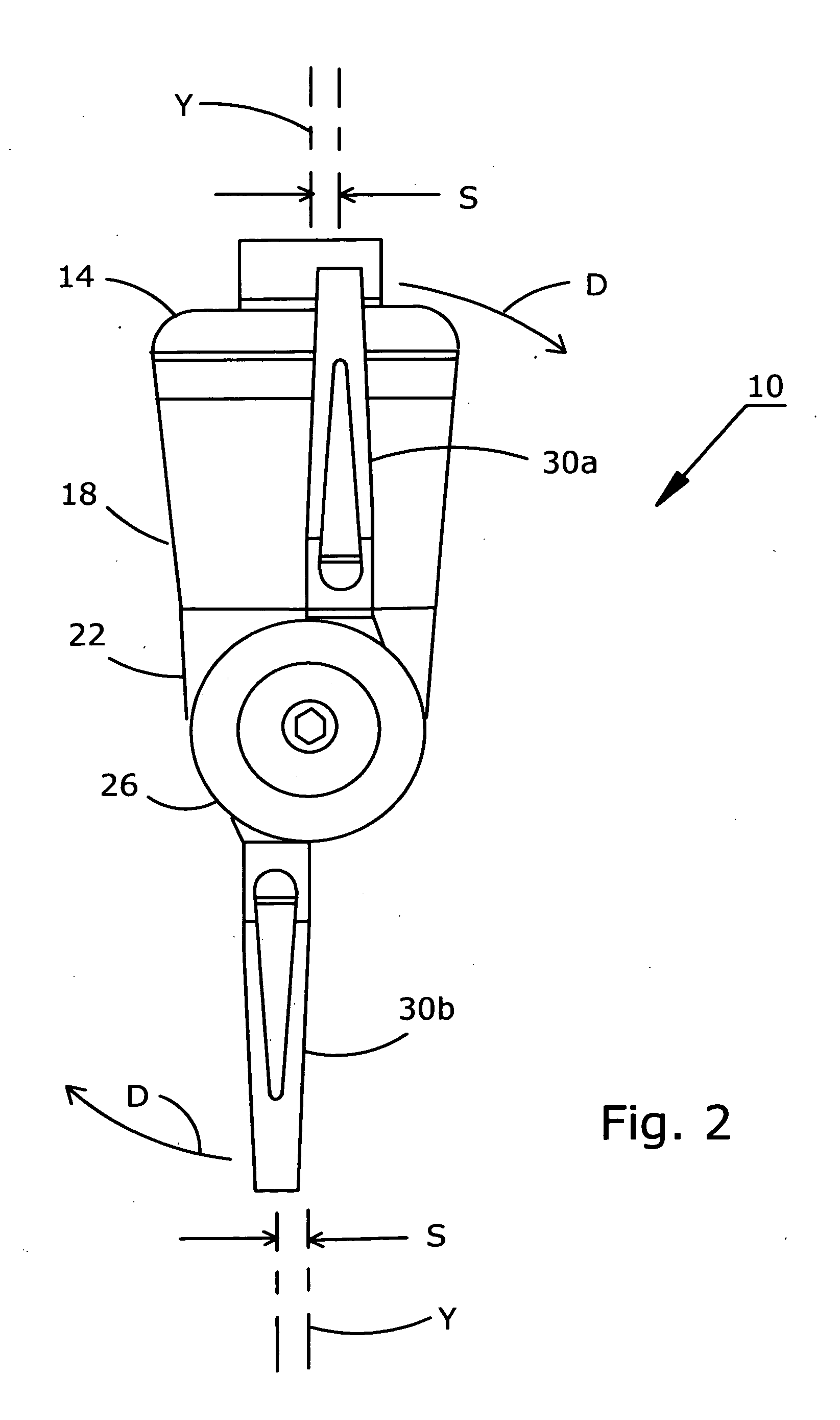
[0020]Referring to FIG. 1, the rotary impingement cleaning apparatus of the present invention is designated generally by numeral 10. Cleaning apparatus 10 is typically oriented for use with axis Y substantially vertical and axis X substantially horizontal. A pressurized cleaning liquid is introduced into cleaning apparatus 10 through inlet cap 14 in the direction indicated by arrow A and discharged from cleaning apparatus 10 through nozzles 30a and 30b in the directions indicated by arrows B. Inlet cap 14 is fixedly mounted to an entry of a housing 18. An elbow 22 is mounted to an exit of housing 18 in a manner to allow elbow 22 to rotate around axis Y relative to housing 18. A nozzle housing 26 is mounted to elbow 22 in a manner to allow nozzle housing 26 to rotate around axis X relative to elbow 22. Therefore, housing 18 remains stationary while elbow 22 rotates around axis Y and nozzle housing 26 rotates around axis X. Nozzles 30a, 30b are fixedly mounted to nozzle housing 26 to ...


PUM


Abstract

A rotary impingement cleaning apparatus is configured for use in sanitary environments with a minimum of components to enable easy inspection and cleaning. The components of the cleaning apparatus are formed to fit relatively loosely to one another and promote self flushing and self drainage of cleaning liquid. A stator is mounted within a housing for diverting the flow of the pressurized cleaning liquid from axial to angular to impinge and rotationally drive a rotator stem or a rotor. The rotator stem or rotor causes an elbow to rotate around the vertical axis and a number of nozzles mounted to a nozzle housing to rotate around the horizontal axis.

Description

RELATED APPLICATION[0001]This application is a conversion of provisional application No. 61 / 278,067 filed on Oct. 2, 2009.FIELD OF THE INVENTION[0002]The present invention relates to the field of rotary impingement cleaning apparatus, and more particularly to rotary impingement cleaning apparatus adapted for use in sanitary environments such as processing or storage tanks for dairy products, pharmaceuticals or comestibles.BACKGROUND OF THE INVENTION[0003]The dairy, food and pharmaceutical industries use tanks for processing and for storing highly sensitive products. Common preparation processes may include blending, homogenizing, chilling, heating and pasteurizing. Food, cosmetic and pharmacologic ingredients are particularly susceptible to microbial contamination. In addition, process control requires avoiding of any unintended cross-contamination of components from one product type to another. Therefore, thoroughly cleaning of processing tanks between production batches and when c...

Claims


Application Information

Patent Timeline
IPC IPC(8): B08B3/00
CPCB08B9/0936B05B3/0445
Inventor DELANEY, ROBERT E.DELANEY, ANDREW K.DEBEAUPRE, JOHNNY A.MOLUGU, SUNEETH D. A.
Owner ALFA LAVAL ASHBROOK SIMON HARTELY INC
Why Eureka
Try Eureka