Multifunctional energy management building cladding

a multi-functional, building technology, applied in the direction of transportation and packaging, thermal-pv hybrid energy generation, lighting and heating apparatus, etc., can solve the problems of reducing air quality, increasing the cost of energy required to cool a conditioned space, and increasing the temperature of the side lap joint. , to achieve the effect of increasing the weather tightness of the side lap join

Inactive Publication Date: 2011-01-06
BOTKE MATTHEW MURRAY
View PDF10 Cites 17 Cited by
  • Summary
  • Abstract
  • Description
  • Claims
  • Application Information

AI Technical Summary

Benefits of technology

[0045]FIG. 16 is a front view (16A) and a back view (16B) of one embodiment as a shingle illustrating an ornamental accent or shadow line on the front surface as well as the location sealant might be used to increase the weather-tightness of the side lap joint.

Problems solved by technology

The rate of energy transfer across the building envelope becomes significant when large temperature differences exist between the ambient environment and the conditioned space.
Traditionally, the energy required to cool a conditioned space is more expensive than the equivalent energy required for heating the same space due to the type of energy required for each application.
Heating is typically accomplished by burning fossil fuel while cooling is typically accomplished using more costly electrical energy.
The effects of local air heating in regions with a high proportion of absorbing surfaces such as in developed areas is known as the Heat Island Effect and can be a significant source of heat gain into buildings as well as result in decreased air quality.
While bare metals are excellent reflectors, these materials do not effectively emit heat energy compared to other building materials such as paint and masonry (emissivity>0.70).
Several disadvantages occur as a result of using polished bare metal as a cladding surface such as that described in U.S. Pat. No. 3,001,331 granted to Brunton.
The cladding is subjected to larger temperature cycling amplitudes, which degrade the useful life of the system.
Also, higher cladding temperatures increase the thermal gradient between the inside and outside of the building envelope causing an increase in energy transfer rate.
Another disadvantage of the referenced art is that polished metal surfaces must be chosen to withstand the effects of the environment without degrading appreciably in reflectivity, which further limits the applicability in both choice of material and economical manufacturing for a reflective surface.
Metals such as copper, iron, steel and aluminum for example do not remain bright when exposed to the weathering effects of the environment unless sufficiently protected with a coating.
An overhanging surface is not effectively self-cleaning except in heavy rains and therefore tend to trap debris.
This often leads to degradation and discoloration from environmental fouling and thus results in reduced solar performance and negative ornamental appearance.
Further, overhanging surfaces increase manufacturing complexity for molded cladding such as tiles.
The exposure of the reflective surface sufficiently enough to be perceived in the visual field of people viewing the cladding from normal viewing positions creates a negative ornamental appearance.
The extruding process is capable of producing overhanging surfaces but not capable of producing features required for inclined surface cladding such as the side lap and gutter for tiles.
Although an object of the referenced art is to preserve ornamental appeal, the art as described relies on refraction and is therefore very sensitive to environmental fouling.
A disadvantage of this technology is that reflectivity is limited to approximately only one-half of the incident solar energy on the building.
Wavelength selective reflectivity addresses the importance of ornamental appeal for visible building cladding but does not exploit the advantages of sun angle responsive selective reflectivity.
Traditionally, this equipment has not been well integrated to the cladding system but rather attached over the cladding system.
As a result, equipment placement is often not ideal from a performance aspect and therefore operates at reduced effectiveness.

Method used


Image

  • Multifunctional energy management building cladding
  • Multifunctional energy management building cladding
  • Multifunctional energy management building cladding

Examples


third embodiment

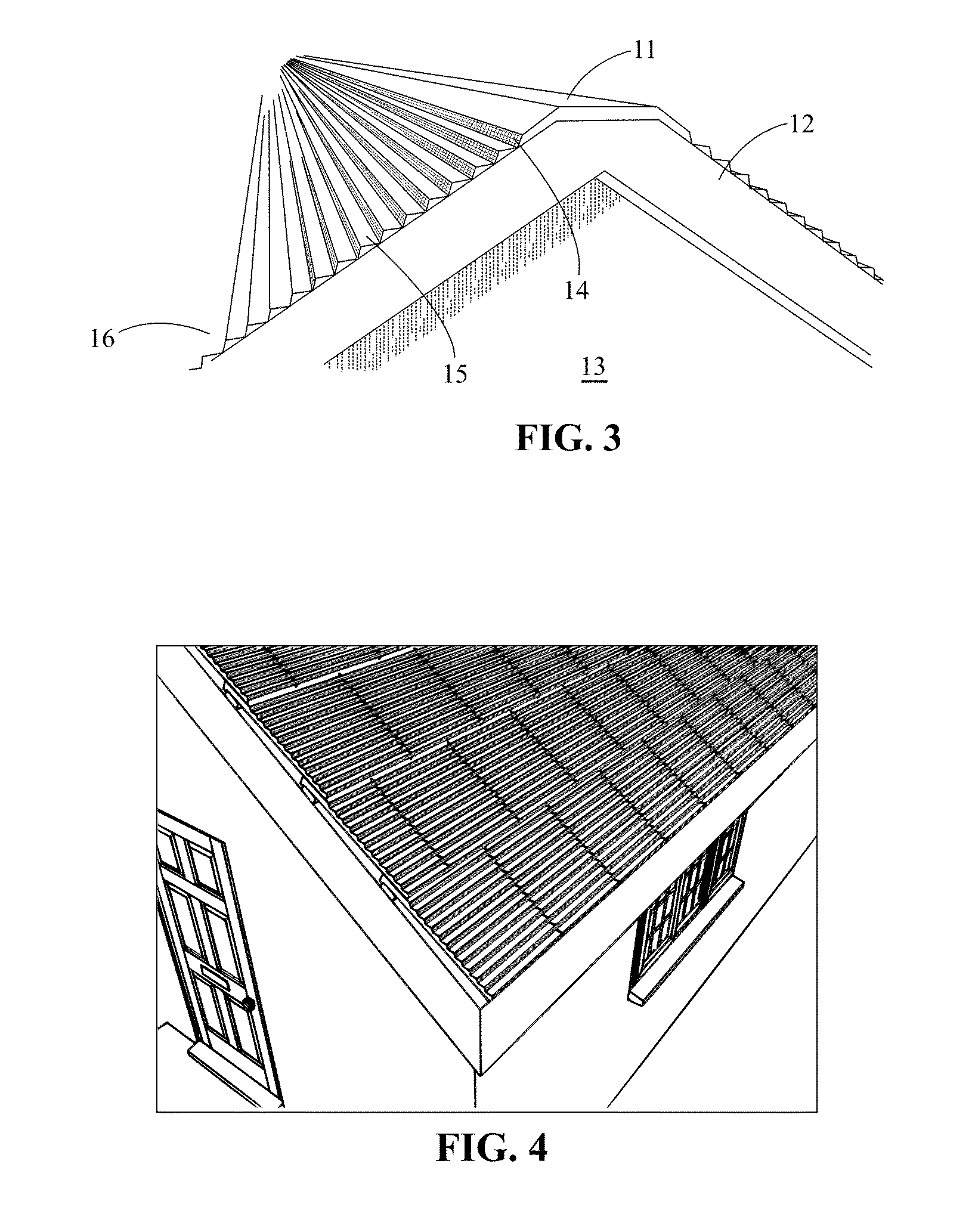
[0072]FIG. 24 illustrates the cladding currently contemplated as a cladding system, which includes a region of the cladding shown in detail in FIG. 25. A region (51) of the building cladding (52) is illustrated in FIG. 25 whereby horizontal surfaces (15) exhibit higher absorptivity than the remainder of the building cladding horizontal surfaces. FIG. 26 is a cross sectional view of the region in FIG. 25. FIG. 26A illustrates the cladding (51) assembled on an inclined building substrate (30). FIG. 26B illustrates an exploded view of the same section in FIG. 26A. A plurality of tubes (56) or other means for fluid or gas containment and transport is in thermal communication with interior surfaces (29) of the cladding and located within the horizontal channels (31). A working fluid circulated in the tubes absorbs energy from the cladding, which is then transported away from the cladding. As but some examples of working fluids include air, water, glycerin, polypropylene glycol, polyethyl...

fourth embodiment

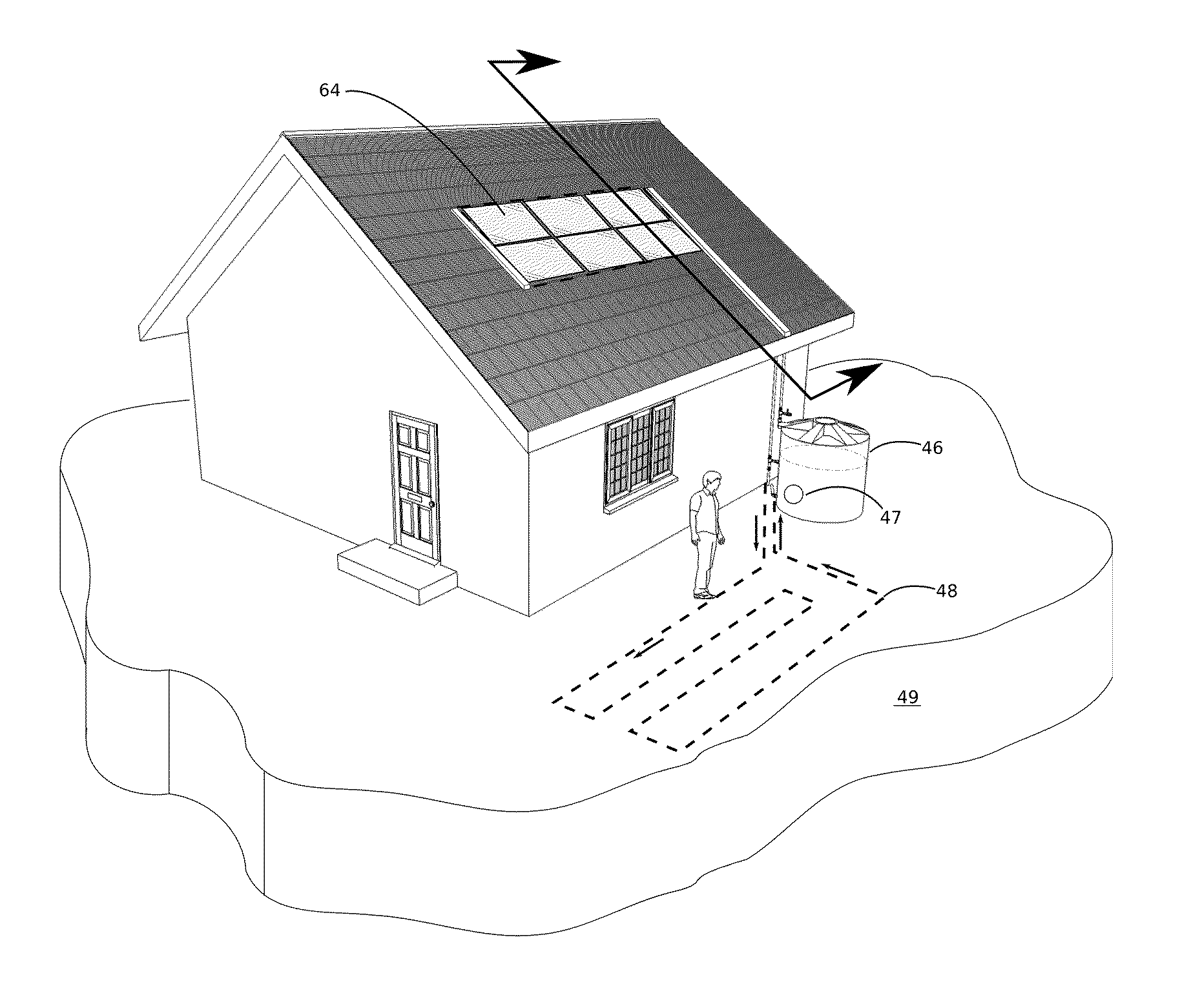
[0073]FIG. 24 illustrates the cladding system currently contemplated, which includes a region of the cladding shown in detail in FIG. 28. A cladding region over the roof eaves terminating at the fascia (16) of the building is illustrated in FIG. 28 and is typically where ice dams form in cold climates. A cladding according to this invention mitigates the formation of ice dams by circulating a working fluid (61) at a temperature sufficiently above 0-deg Celsius under the cladding in order to preclude water freezing and or melting frozen water on the cladding. Fluid input (54) is preferably above 30-deg Celsius and the fluid output (55) is preferably above 5-deg Celsius and even more preferably above 10-deg Celsius. An alternative heating means utilizes electrical heaters positioned in the channels (31) in thermal communication with the cladding surfaces (29) of at least the courses of cladding units directly over the eaves. Electrical wires service the heaters and are routed within t...

fifth embodiment

[0074]A fifth embodiment currently contemplated utilizes means to generate electrical energy from incident solar radiation affixed to or as the substantially horizontal surfaces. As an example, photovoltaic devices may be affixed to the surfaces (15) of the shingle illustrated in FIG. 8. Any combination of the entire clad building surface or selected regions such as the region (51) shown in FIG. 25 may be configured to generate electricity especially when the sun is at high elevation angles. Electrical wires and components such as inverters, and connectors are housed and routed within the channels (31) of the cladding and are then routed through the conduits (45,50) thereby minimizing substrate penetrations. Electrical connections can also be established within the overlapping region (37) of adjacent shingles. The outward facing surfaces of conduits can also be configured to generate electricity such as by photovoltaic devices (53). Energy conversion from one form to another generat...


PUM


Abstract

This invention relates to a building cladding for inclined surfaces such as for a sloped roof. More specifically, this invention relates to a building cladding that is passively responsive to sun elevation angles, is multi-functional, and is substantially uniformly ornamental when viewed from common viewing positions. The cladding is predominantly comprised of pairs of substantially horizontal and vertical surfaces extended horizontally and repeated vertically or along the incline of the building substrate. Substantially horizontal surfaces may be adapted for absorbing solar energy, reflecting solar energy, generating electricity from solar energy, converting solar energy into another form of energy, and or ornamentally matching substantially vertical surfaces.

Description

CROSS REFERENCE TO RELATED APPLICATIONS[0001]I claim the benefit of the following applications;[0002]U.S. Provisional Application No. 61 / 270,033 filed on Jul. 3, 2009 entitled Reflective Building Element According to Sun Angles with High Emissivity [0003]U.S. Provisional Application No. 61 / 273,331 filed on Aug. 3, 2009 entitled Building Integrated Solar Energy Management Cladding and Method Thereof STATEMENT REGARDING FEDERALLY SPONSORED RESEARCH OR DEVELOPMENT[0004]Not ApplicableTHE NAMES OF THE PARTIES TO A JOINT RESEARCH AGREEMENT[0005]Not ApplicableREFERENCE TO SEQUENCE LISTING, A TABLE OR A COMPUTER PROGRAM LISTING COMPACT DISC APPENDIX[0006]Not ApplicableBACKGROUND OF THE INVENTION[0007]This invention relates to an outer covering or cladding of a building envelope for inclined surfaces such as for a sloped roof. More specifically, this invention relates to a multi-functional cladding passively responsive to sun elevation angles and substantially uniformly ornamental when viewe...

Claims


Application Information

Patent Timeline
Patent Type & Authority Applications(United States)
IPC IPC(8): E04D13/18
CPCE04D1/06Y10T428/24479E04D1/18E04D3/30E04D13/103E04D13/17F24D2200/14F24J2/045Y02B10/12Y02B10/20Y02B10/70Y02E10/44Y02B80/34Y02E10/60H02S20/23H02S40/44Y10T428/24628E04D1/16E04D1/30F24S20/67Y02B10/10Y02B80/00Y02E10/40Y02E10/50Y02A30/254
Inventor BOTKE, MATTHEW MURRAY
Owner BOTKE MATTHEW MURRAY
Why Eureka
Try Eureka