
Variable volume bioreactor

a bioreactor and variable volume technology, applied in the field of bioreactors, can solve the problems of significant restrictions that hinder the application of bioreactors, limited success of the practicable use of bioreactors, and inability to provide tight volume control

Inactive Publication Date: 2011-03-31
WRIGHT IAN MALCOLM
View PDF25 Cites 12 Cited by
  • Summary
  • Abstract
  • Description
  • Claims
  • Application Information

AI Technical Summary

Benefits of technology

The present invention is a bioreactor that can be used for culturing cellular biological material in solid particles. The bioreactor includes a rigid core with a light source, an outer expandable growth containment portion, and a lower end portion for supplying culture medium. The bioreactor allows for constant density of cells by keeping the volume of the cellular material constant with respect to the volume of the culture medium. The bioreactor can be adapted for different applications such as growing carbon dioxide sequestrating biological material, methane digestion, fuel production, or water production. The bioreactor is designed to provide optimal conditions for growth of biological material and can be adjusted to suit different needs.

Problems solved by technology

The practical use of bioreactors has had limited success due to the cost of building and maintaining the bioreactor vessels and also the difficulty in removing the products from the reactor vessel once mature.
The two types of devices providing for variable volume during cell culture without compromising sterility of the culture that have been described, moreover, present significant restrictions that hinder their application.
Several forms of a chamber for cell culture based on a bag, which conceptually could allow variable volumes for cultures, have been described previously (e.g., U.S. Pat. Nos. 5,686,304 and 5,714,384), but the flexible walls present in these and other bags do not provide tight control of volumes, do not provide rigid surfaces for culture of adherent cells, nor present chambers with well-defined geometries for well-defined perfusions (e.g., uniform hydrodynamic shear stresses required for many adherent cells).
Deformability of a wall of a chamber in general (e.g., as practiced by U.S. Pat. No. 6,152,163), leads to these inherent limitations.
This type of design, similar in concept to other piston-based designs for biotechnological applications described in U.S. Pat. Nos. 5,143,847, 6,007,472, and 6,290,910, are cumbersome mechanically and not well-suited to large, planar cultures of adherent monolayers.

Method used


Image

  • Variable volume bioreactor
  • Variable volume bioreactor
  • Variable volume bioreactor

Examples


Embodiment Construction

[0091]According to a preferred aspect of the present invention, an expandable bioreactor is provided.

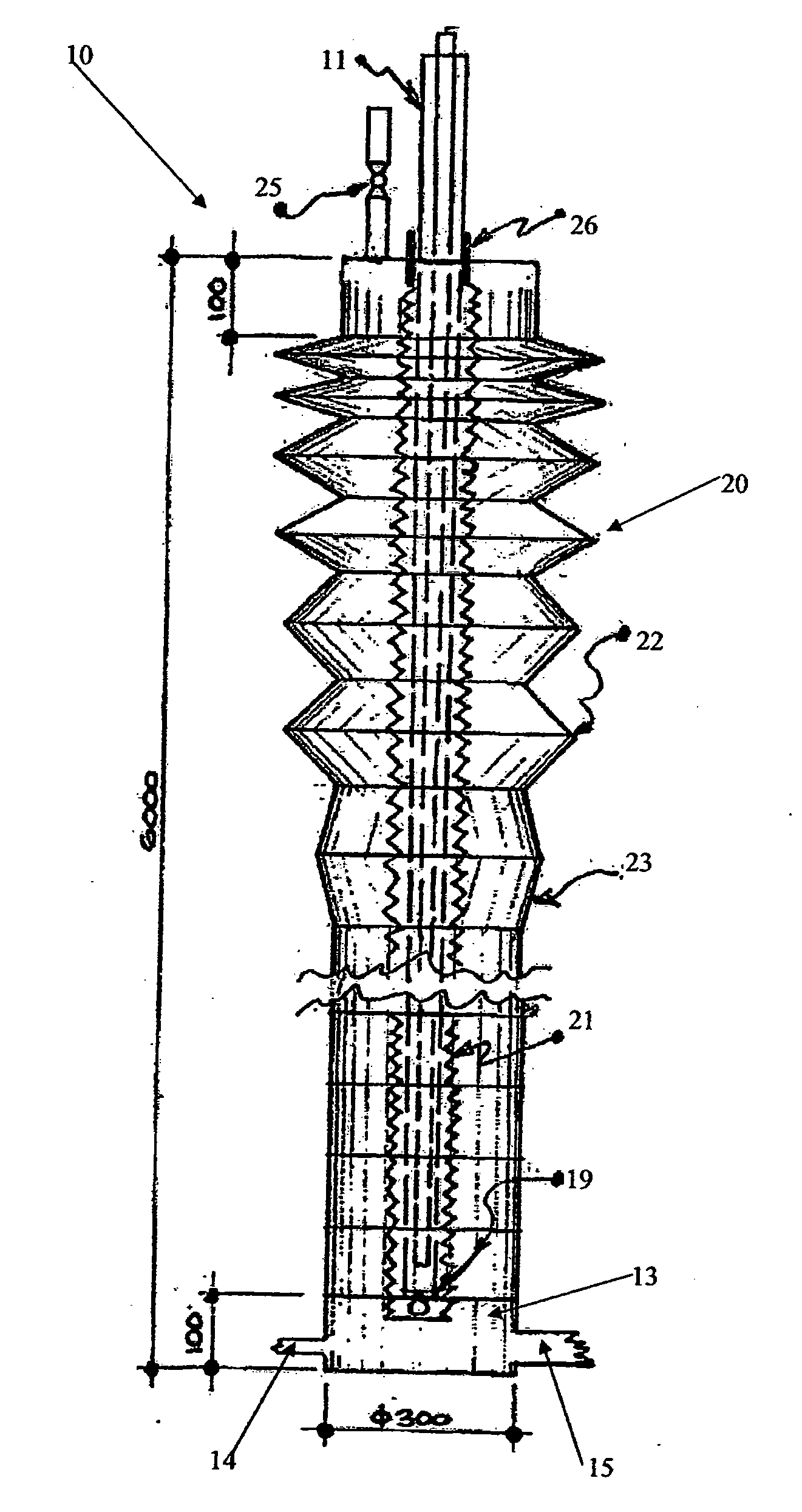
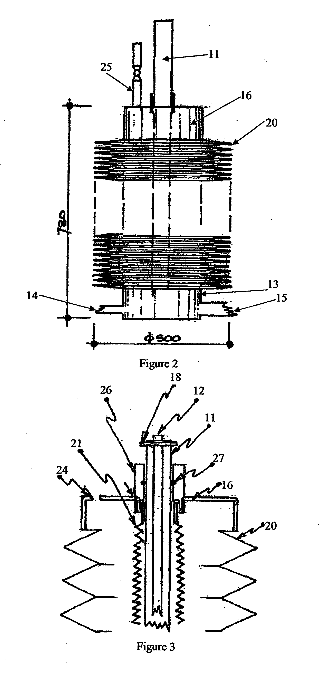
[0092]The bioreactor 10 of the illustrated embodiment includes a rigid core 11 associated with a light source 12, an outer expandable growth containment portion located concentrically about the rigid core 11, a lower end cap 13 with an inlet 14 to supply culture medium and an outlet 15, and an upper end cap 16 with an opening 17 therein through which the rigid core 11 passes.

[0093]The rigid core 11 of the illustrated embodiment is oriented substantially vertically. The core 11 is formed of a hollow tubular member which is cylindrical.

[0094]The core 11 is manufactured of a translucent plastic such as translucent PVC. As illustrated in FIG. 1 in particular, the core 11 is longer (higher) then the length (height) of a containment portion expended to maximum expansion.

[0095]The core 11 is maintained substantially vertically by an overhead fixing frame 18. The fixing frame 18 is attached ...


PUM

PropertyMeasurementUnit
diameteraaaaaaaaaa
lengthaaaaaaaaaa
heightaaaaaaaaaa

Abstract

A variable volume bioreactor including a rigid core associated with a light source, an outer expandable growth containment portion located concentrically about the rigid core, a lower end portion associated with an inlet to supply culture medium and an outlet, and an upper end cap with an opening therein through which the rigid core passes, wherein the outer containment portion expands as the cellular biological material contained in said portion grows and expands.

Description

FIELD OF THE INVENTION[0001]The present invention relates to bioreactors and particularly to low cost, reusable bioreactors.BACKGROUND ART[0002]For many years, bioreactors have been considered to be an ideal technical solution for the growing of feedstock for the extraction of oils. Bioreactors have also been suggested as a method to remove carbon dioxide from industrial emissions. The practical use of bioreactors has had limited success due to the cost of building and maintaining the bioreactor vessels and also the difficulty in removing the products from the reactor vessel once mature.[0003]Bioreactors degrade contaminants in water with microorganisms through attached or suspended biological systems. In suspended growth systems, such as activated sludge, fluidized beds, or sequencing batch reactors, contaminated ground water is circulated in an aeration basin where a microbial population aerobically degrades organic matter and produces CO2, H2O, and new cells. The cells form a slu...

Claims


Application Information

Patent Timeline
Patent Type & Authority Applications(United States)
IPC IPC(8): C12M1/00
CPCC12M21/02C12M31/08C12M23/34C12M23/26C12M41/44
Inventor WRIGHT, IAN MALCOLM
Owner WRIGHT IAN MALCOLM
Learn More