
Radiographic image capturing apparatus and radiographic image capturing method

a radiographic image and imaging apparatus technology, applied in the direction of instruments, patient positioning for diagnostics, applications, etc., can solve the problems of inaccurate tissue of biopsy region cannot be properly sampled by the biopsy apparatus, etc., to achieve accurate three-dimensional position of biopsy region calculation

Inactive Publication Date: 2011-03-31
FUJIFILM CORP
View PDF23 Cites 17 Cited by
  • Summary
  • Abstract
  • Description
  • Claims
  • Application Information

AI Technical Summary

Benefits of technology

It is an object of the present invention to provide a radiographic image capturing apparatus and a radiographic image capturing method which prevent a subject from being unduly exposed to radiation and accurately calculate the three-dimensional position of a biopsy region in an object to be examined by reliably performing a stereographic image capturing process on the biopsy region.
With the radiographic image capturing apparatus and the radiographic image capturing method described above, based on the three-dimensional position of the biopsy region which is obtained in a present stereographic image capturing process, an irradiated field (new irradiated field) of the radiation in a next stereographic image capturing process is calculated, and the next stereographic image capturing process is performed with the calculated new irradiated field. Since the radiation is applied in the new irradiated field around the biopsy region in the next stereographic image capturing process, the radiation is prevented from being applied to body regions of the subject which have nothing to do with the calculation of the three-dimensional position of the biopsy region, and hence the subject is prevented from being unduly exposed to the radiation.
Even if the object is moved or positionally or angularly changed between stereographic image capturing processes or the radiation source disposed at the two angles suffers angular errors, since the new irradiated field around the biopsy region is irradiated with the radiation in the next stereographic image capturing process, two radiographic images acquired in the next stereographic image capturing process reliably cover the biopsy region. Consequently, it is possible to perform a stereographic image capturing process on the biopsy region and to accurately calculate the three-dimensional position of the biopsy region regardless of a movement or positional or angular change of the object or angular errors of the radiation source.
According to the present invention, therefore, the subject is prevented from being unduly exposed to the radiation, and a stereographic image capturing process is reliably performed on the biopsy region in the object to be examined to accurately calculate the three-dimensional position of the biopsy region.
If any movement or positional or angular change of the object between stereographic image capturing processes is small, then the irradiated field calculation control unit enables the irradiated field calculating unit to calculate the new irradiated field for thereby preventing the subject from being unduly exposed to the radiation. On the other hand, if the object is greatly moved or positionally or angularly changed between stereographic image capturing processes, then the irradiated field calculation control unit disables the irradiated field calculating unit from calculating the new irradiated field, and the radiation is applied to the object to be examined in a wider irradiated field, for thereby allowing the biopsy region to be reliably covered by a radiographic image.
It is thus easy to confirm whether there exists any obstacle to a stereographic image capturing process between the radiation source and the object to be examined, before the stereographic image capturing process is carried out.

Problems solved by technology

If the biopsy region is included in only one or neither of the two radiographic images, then the three-dimensional position of the biopsy region cannot be calculated accurately.
As a result, the tissue of the biopsy region cannot properly be sampled by the biopsy apparatus.

Method used


Image

  • Radiographic image capturing apparatus and radiographic image capturing method
  • Radiographic image capturing apparatus and radiographic image capturing method
  • Radiographic image capturing apparatus and radiographic image capturing method

Examples


Embodiment Construction

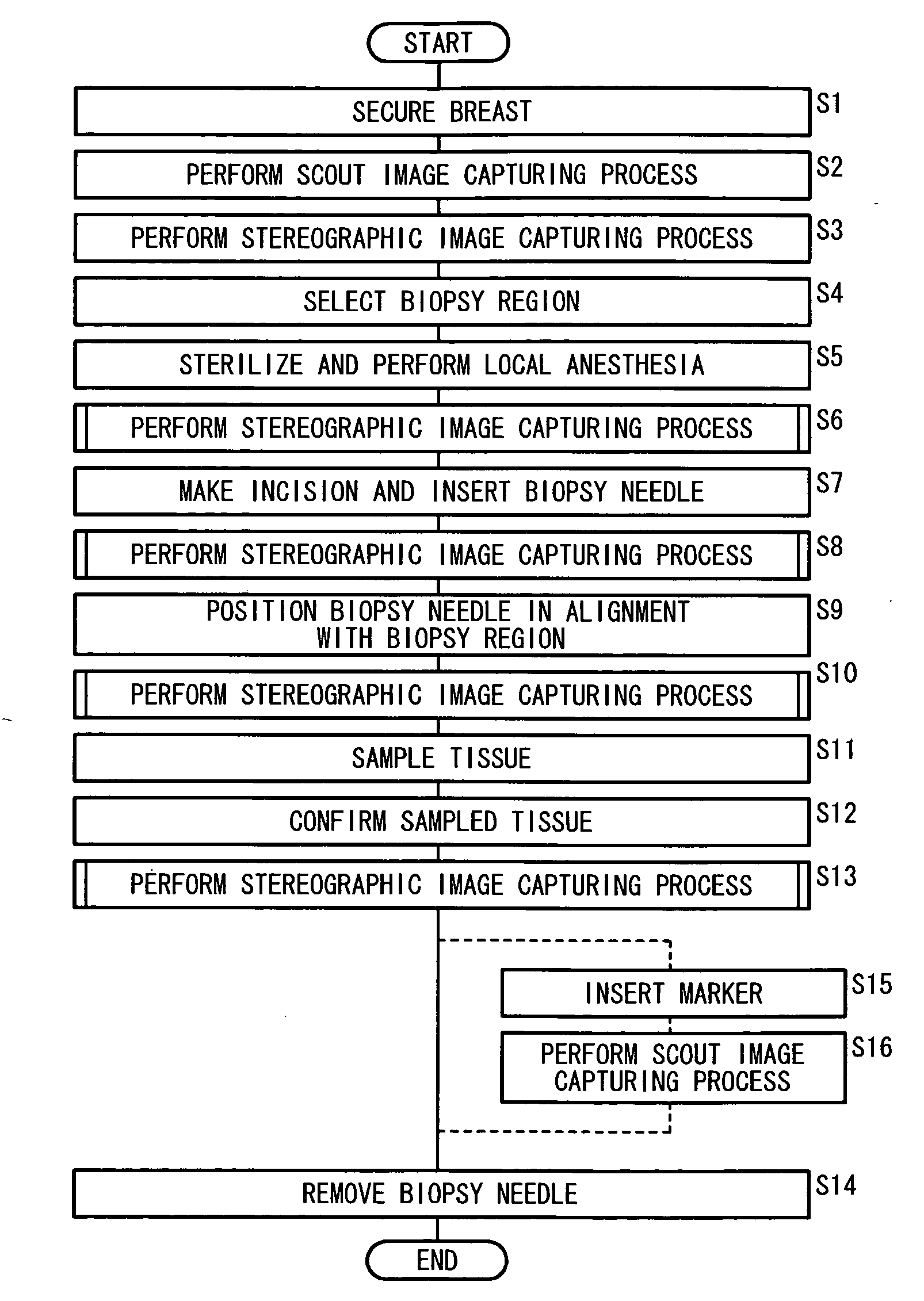
A radiographic image capturing apparatus and a radiographic image capturing method according to a preferred embodiment of the present invention will be described below with reference to FIGS. 1 through 10 of the accompanying drawings.

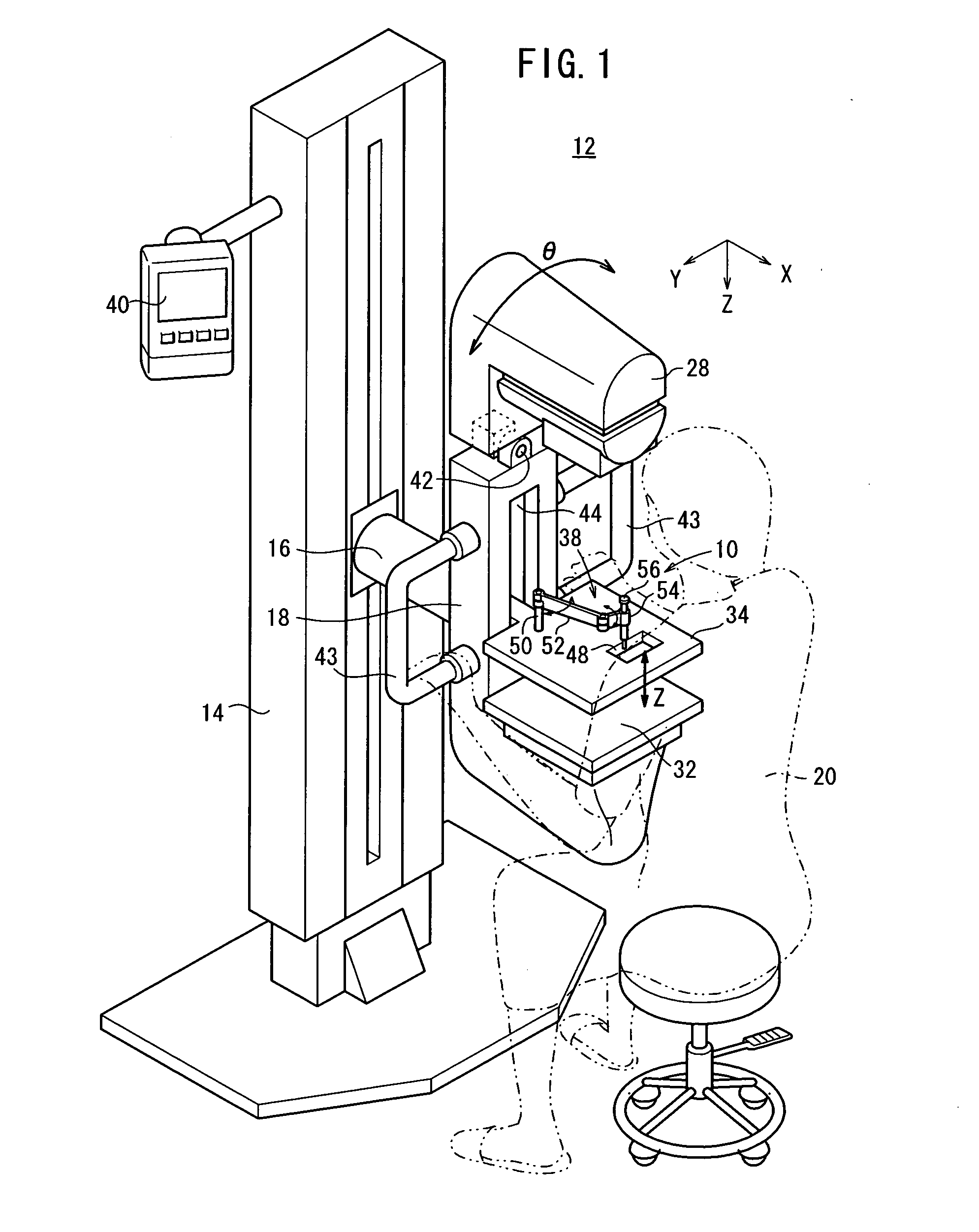
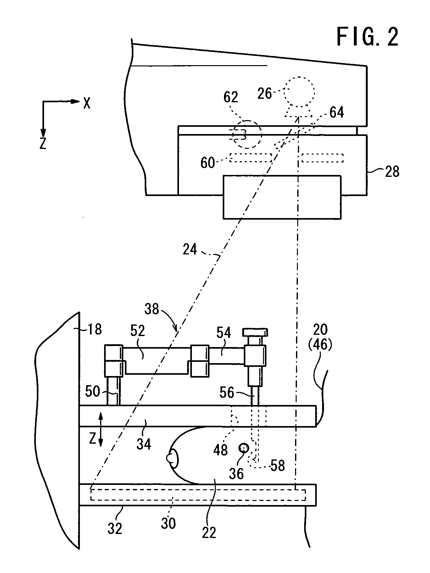
The basic structure of a mammographic apparatus 12 serving as the radiographic image capturing apparatus according to an embodiment of the present invention which incorporates a biopsy apparatus 10 will be described below with reference to FIGS. 1 and 2.

The mammographic apparatus 12 basically includes an upstanding base 14, a vertical arm 18 fixed to the distal end of a swing shaft 16 disposed substantially centrally on the base 14, a radiation source housing unit 28 fixed to an upper end of the arm 18 and housing therein a radiation source 26 for applying radiation 24 to a breast 22 as an object to be examined of an examinee (subject) 20, an image capturing base 32 mounted on a lower end of the arm 18 and housing therein a solid-state detector (radiati...


PUM


Abstract

In a radiographic image capturing apparatus, a biopsy region positional information calculator calculates a three-dimensional position of a biopsy region in an object to be examined based on two radiographic images which are acquired in a stereographic image capturing process, an irradiated field calculator calculates a new irradiated field covering the biopsy region based on the calculated three-dimensional position of the biopsy region and two angles at which a radiation source is disposed in the stereographic image capturing process, and a collimator controller controls a collimator to change the irradiated field of the radiation to the new irradiated field in a next stereographic image capturing process.

Description

CROSS-REFERENCE TO RELATED APPLICATIONThis application is based upon and claims the benefit of priority from Japanese Patent Application No. 2009-224505 filed on Sep. 29, 2009, of which the contents are incorporated herein by reference.BACKGROUND OF THE INVENTION1. Field of the InventionThe present invention relates to a radiographic image capturing apparatus and a radiographic image capturing method for irradiating an object to be examined of a subject with radiation emitted from a radiation source while an irradiated field of the radiation on a radiation detector is being delimited by a collimator, and converting the radiation that has passed through the object to be examined into a radiographic image with the radiation detector.2. Description of the Related ArtThere have heretofore been developed biopsy apparatus for sampling a tissue of a biopsy region (e.g., a lesion region in a subject's breast) in an object to be examined of a subject and thoroughly examining the sampled tiss...

Claims


Application Information

Patent Timeline
Patent Type & Authority Applications(United States)
IPC IPC(8): A61B6/02
CPCA61B6/022A61B6/0414A61B6/06A61B6/12A61B2019/5238A61B6/488A61B6/502A61B6/542A61B10/0283A61B6/469A61B2090/376
Inventor OKADA, NAOYUKINAKATA, HAJIMENAKAYAMA, HIROKIYOSHIDA, TAKAO
Owner FUJIFILM CORP
Learn More