
Information-processing equipment

a technology of information processing equipment and folding, which is applied in the direction of instruments, portable computer details, electric apparatus casings/cabinets/drawers, etc., can solve the problems of increasing the manufacturing cost of the hinge mechanism, severely damage the hinge mechanism, and the display section accommodated in the first chassis side is subject to a larger damage than the operation control section of the second chassis side, etc., to achieve simple constitution, increase manufacturing cost, and reduce damage at the display section and/or the hinge mechanism

Active Publication Date: 2011-03-31
PANASONIC CORP
View PDF4 Cites 0 Cited by
  • Summary
  • Abstract
  • Description
  • Claims
  • Application Information

AI Technical Summary

Benefits of technology

[0008]The present invention was made in view of the foregoing technical problems. A basic object of the present invention is to enable to suppress the damage caused at the display section and / or the hinge mechanism by a simple constitution, in the openable and closable folding information-processing equipment, when an impact load is applied from the front side of the information-processing equipment, without increasing the manufacturing cost and without detracting the convenience in carrying the equipment in folded state.
[0011]Therefore, when an impact load is applied from the front side (the second side) to the information-processing equipment, for example by a front-first dropping, the impact load is hardly inputted into the front side surface of the first chassis as compared to the front side surface of the second chassis. Thereby, it is possible to suppress the display section accommodated in the first chassis from subjecting to a large damage also to suppress the hinge mechanism from subjecting to a large damage. That is, according to the present invention, it is possible to obtain the above explained function and effect by the simple constitution which is only to devise the shape of the other side (the second side: i.e. the front side), in the planar view, of the first chassis and the second chassis, without increasing the manufacturing cost and without detracting the convenience in carrying the equipment in folded state.
[0014]Therefore, when an impact load is applied from the front side (the second side) to the information-processing equipment, for example by a front-first dropping, the impact load is hardly inputted into the projecting end surface of the operation member as compared with the central portion and the front side surface near thereto. Thereby, it is possible to suppress the operation member from subjecting to a large damage.
[0017]Therefore, when an impact load is applied from the front side (the second side) to the information-processing equipment, for example by a front-first dropping, the impact load is hardly inputted into the projecting end surface of the operation member as compared with the central portion and the front side surface near thereto. Thereby, it is possible to suppress the operation member from subjecting to a large damage.

Problems solved by technology

Therefore, as stated above, in the case the front side surface of the first chassis and the front side surface of the second chassis lays side-by-side to form substantially flat face, in a state where the information-processing equipment is folded, the display section accommodated in the first chassis tends to subject to a larger damage than the operation control section of the second chassis side.
Further, the impact load inputted from the front side of the first chassis is transmitted to the hinge mechanism which couples the first chassis to the second chassis in an openable and closable manner, and may severely damage the hinge mechanism.
However, in the constitution disclosed in Japanese Patent Laid-open Publication No. 2005-165475, since the hollow bulge portions are formed at four corners of the second chassis, the shape of the second chassis is complicated and also the manufacturing cost thereof is increase, further, the users feel inconvenience in carrying the laptop PC in a state the first and the second chassis are closed together.

Method used


Image

  • Information-processing equipment
  • Information-processing equipment
  • Information-processing equipment

Examples


Embodiment Construction

[0025]Hereinafter, an embodiment of the present invention will be explained in detail, by taking a so-called laptop PC as an example, with reference to the accompanying drawings.

[0026]In the following description, some terms which respectively indicate specific directions (“up”, “down”, “left”, “right” and other terms include their concept, “clockwise direction”, “counter-clockwise direction”, for example) may be used. However, it is to be noted that those terms are used to facilitate understanding of the present invention with reference to the accompanying drawings. And, the present invention should not be interpreted in a limited way by meanings of those terms.

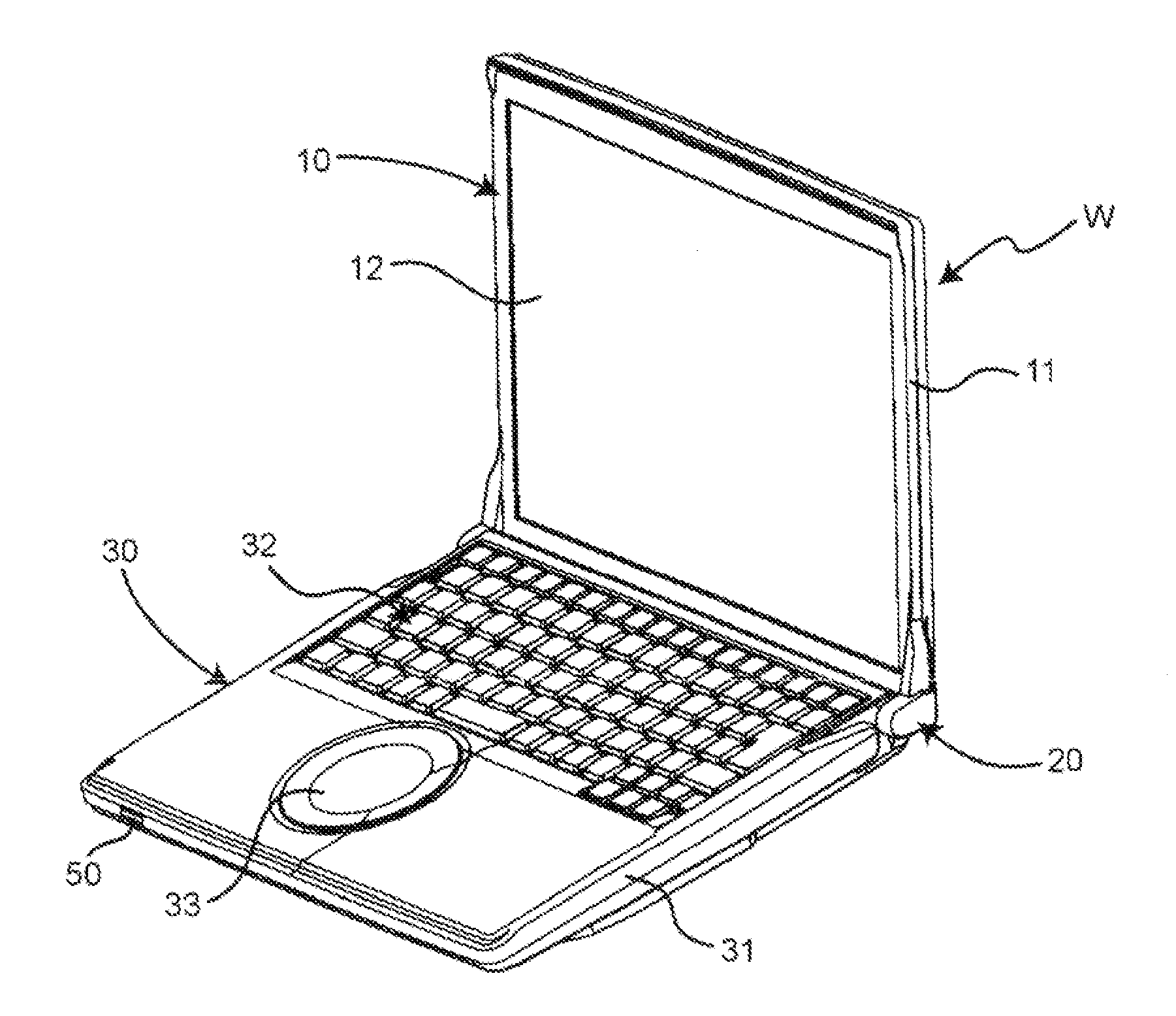
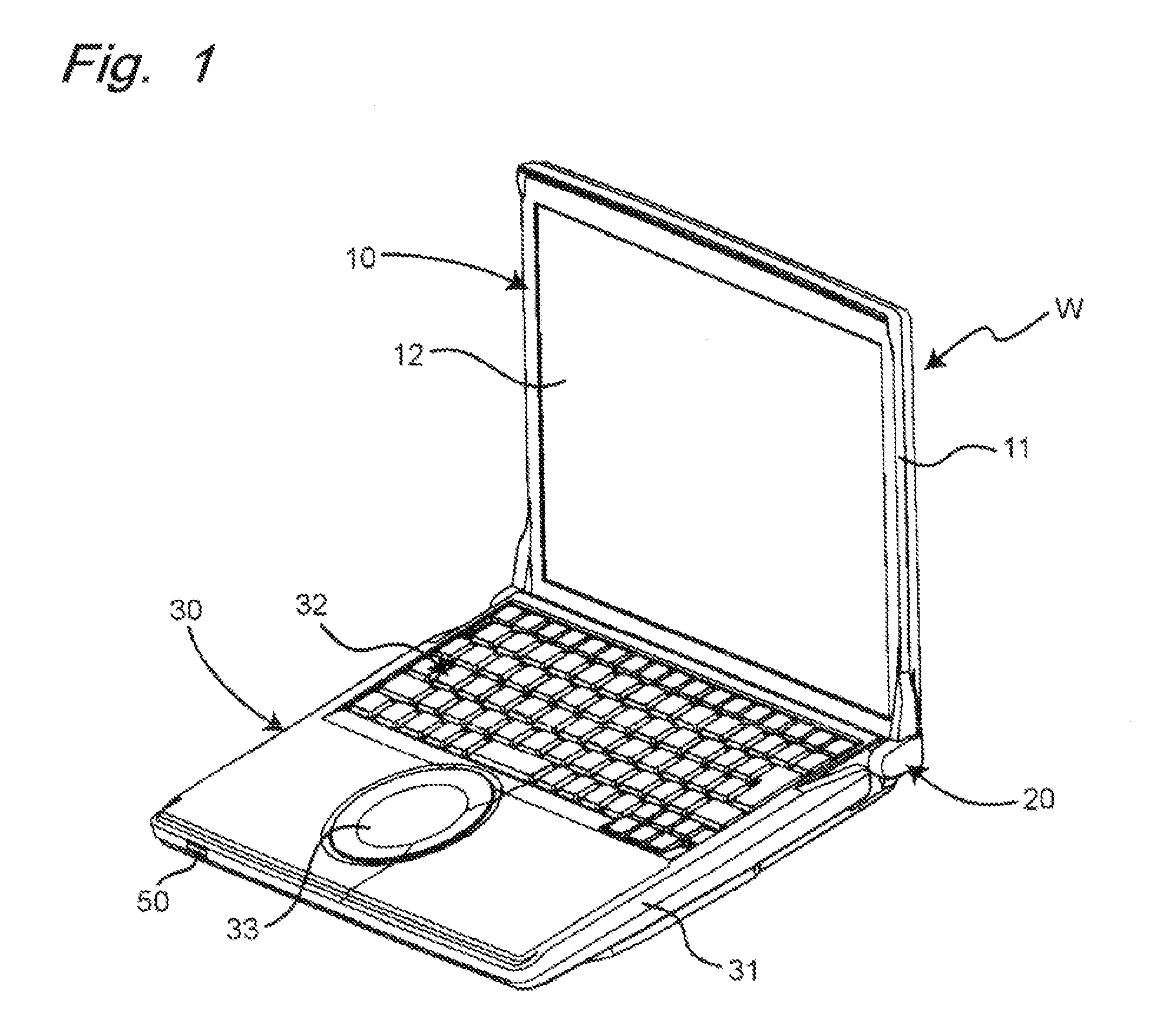
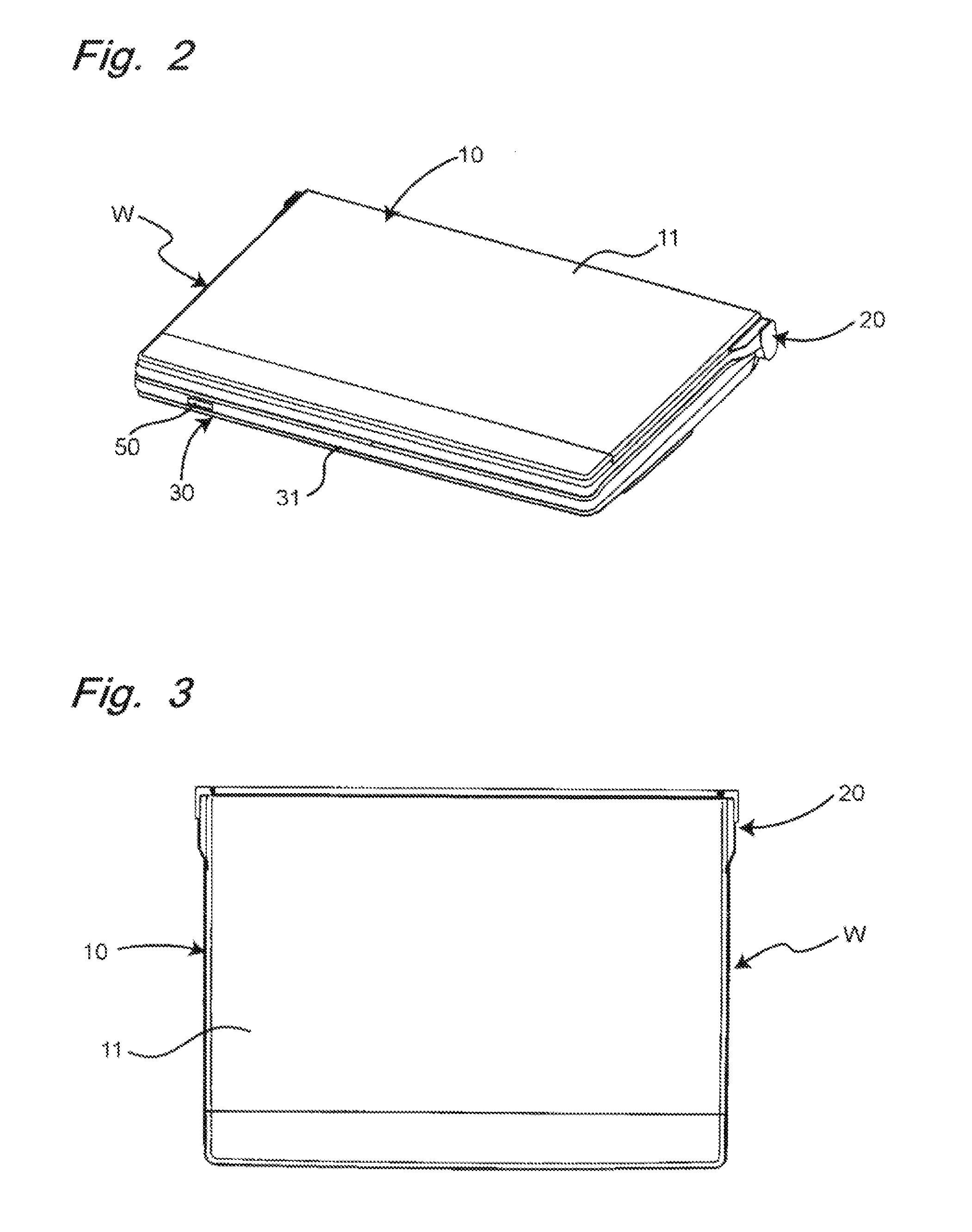
[0027]FIGS. 1 and 2 are perspective views showing the laptop PC according to the present embodiment in an enable state and a nonuse (closed) state. And, FIGS. 3, 4 and 5 are a plane view, a side view and a front view of the laptop PC in the nonuse (closed) state. Further, FIG. 6 is an enlarged plane view showing in close-up ...


PUM


Abstract

There is provided a laptop personal computer comprising: a first chassis accommodating a display section and having a basic shape of substantially rectangle in a planar view; a second chassis accommodating an operation control section and having a basic shape of substantially rectangle in a planar view; and a hinge mechanism for coupling one side of the second chassis and one side of the first chassis and supporting both chassis in a relatively openable and closable manner; wherein an other side parallel to the one side of the first chassis is configured so that only its central portion in a widthwise direction parallel to the one side lays side-by-side to form substantially flat face with an other side of the second chassis in a state where the first chassis is closed together with the second chassis, and wherein the other side of the first chassis is configured, in a planar view, so that the more it departs from the central portion toward an edge portion in the widthwise direction, the more it comes closer to the one side of the first chassis than to the other side of the second chassis in a state where the first chassis is closed together with the second chassis.

Description

BACKGROUND OF THE INVENTION[0001]The present invention relates to an openable and closable folding information-processing equipment, for example a laptop personal computer (hereinafter called “laptop PC” as an abbreviated expression, appropriately), specifically to a structure of chassis in such an information-processing equipment.[0002]As is well known, the chassis of the openable and closable folding information-processing equipment such as a laptop PC and the like, is constituted by a display section side chassis (hereinafter called a “first chassis”, appropriately) which accommodates the display section having a display screen such as a liquid crystal type and an operation control section side chassis (hereinafter called a “second chassis”, appropriately) which accommodates the operation control section capable of generating a display signal which is to be inputted into the display section. Both chassis are coupled together by a hinge mechanism in a relatively openable and closa...

Claims


Application Information

Patent Timeline
IPC IPC(8): G06F1/16
CPCG06F1/1656G06F1/1616
Inventor KAWAMOTO, TETSUYAIWAMOTO, AKIRAFURUJIKU, MASARUNAKATANI, HITOSHITANAKA, SHINTARO
Owner PANASONIC CORP
Learn More