
Dual site imaging camera

a dual-site imaging and camera technology, applied in the field of dual-site imaging cameras, can solve the problems of difficult detection of traditional digital imaging approaches, saturated bright signals, and imaging a modulated source which changes faster than the integration time of imaging

Inactive Publication Date: 2011-03-31
CLEAR ALIGN
View PDF6 Cites 43 Cited by
  • Summary
  • Abstract
  • Description
  • Claims
  • Application Information

AI Technical Summary

Benefits of technology

"The present invention provides an improved camera that can capture two images simultaneously by using switchable elements that switch between two states faster than the integration time of the system. The first and second images are captured by different sites in the camera, and the switchable elements switch between the two states to measure light at different locations in the camera. The first and second images can be used for different purposes, such as for a two-dimensional array of pixels. The camera can be controlled by a microcontroller to select the desired operation of the imaging system. The technical effect of this invention is to provide a faster and more efficient camera for capturing two images simultaneously."

Problems solved by technology

While this has many advantages, it can be a disadvantage when the scene is composed of very bright and very dim signal sources.
If the exposure time is short, the dim signals will not be visible, and if the exposure time is too long, the bright signals will be saturated.
Furthermore, imaging a modulated source which changes faster than the integration time for imaging is difficult to detect using traditional digital imaging approaches.

Method used


Image

  • Dual site imaging camera
  • Dual site imaging camera
  • Dual site imaging camera

Examples


Embodiment Construction

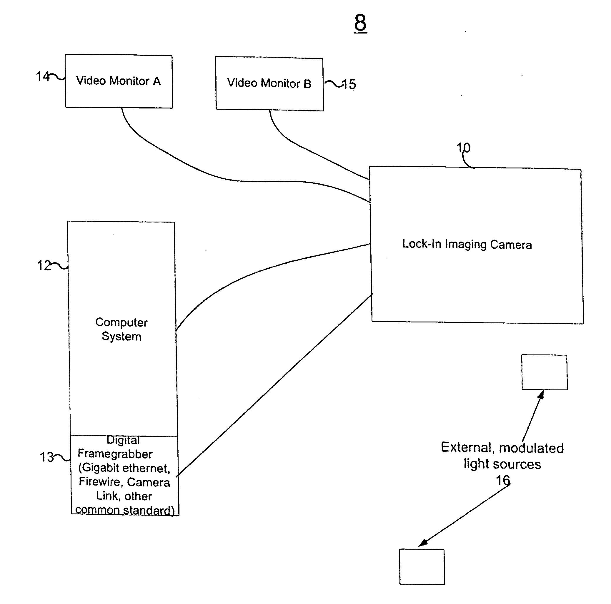
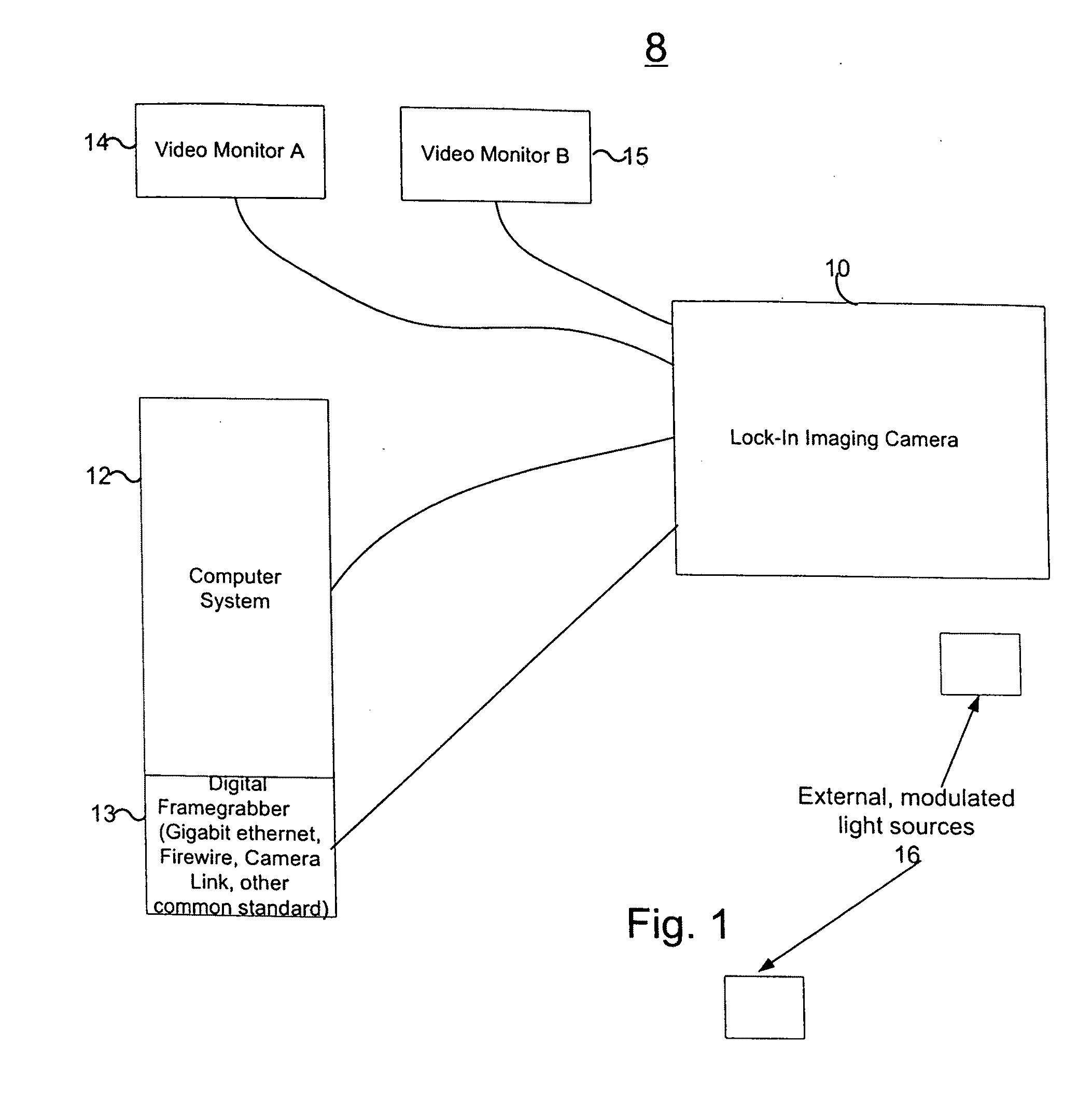
[0032]Referring to FIG. 1, the system 8 is shown using the camera 10 of the present invention. Camera 10 is an electro-optical imaging system that may operate like a typical digital camera. Commands and queries can be sent to and received from the camera over a serial communications link from a personal computer system 12, such as a desktop, laptop, or other programmed microprocessor based system, to control the operation of camera 10.

[0033]Computer system 12 may have components 13 for digital frame capture, such as available from National Instruments line of cards like the PCI-1426, or including types of frame grabbing standards such as Gigabit Ethernet Vision, or Firewire, or high speed USB, or Camera Link. The camera 10 can provide digital representations of the images it captures at a rate of speed commensurate with the live acquisition rate of the camera over an appropriate cable (or wireless) to such components 13 in the computer system 12. The camera 10 also presents a video ...


PUM


Abstract

An imaging system or camera having an array of elements switchable between two states for measuring of light received by the imaging system on a pixel by pixel basis to form two separate images simultaneously over a common integration time in which switching takes place faster than the integration time of the camera. Optical switching may be provided by a spatial light modulator along one of two paths each associated with a detector for one of the images, or each path being associated with one of two non-overlapping regions of the same detector, where each region provides one of the images. Electronic switching may be provided in which for each pixel a photodetector provide an electrical signal onto a switching element which switches the signal onto one of two sites for integrating the signal and providing a pixel value, where the two sites are each associated with a different one of the images.

Description

[0001]This Application claims priority to U.S. Provisional Application No. 61 / 276,429, filed Sep. 11, 2009, which is herein incorporated by reference.FIELD OF THE INVENTION[0002]The present invention relates to a dual site imaging camera (system and method) for capturing two images in the camera over a common exposure time, and particularly to an imaging system which switches on a pixel by pixel basis between two images in measuring light received, to form such images simultaneously over a common integration time, where such switching takes place faster than the integration time of the camera. Switching may be provided optically by a spatial light modulator spatially associated with each of the images in which on a pixel by pixel basis one or more mirrors of the modulator associated with the pixel direct light received along one of two paths having optics for directing such light onto pixel sites of two detectors or two different non-overlapping regions of the same detector associat...

Claims


Application Information

Patent Timeline
Patent Type & Authority Applications(United States)
IPC IPC(8): H04N5/357
CPCG03B39/06H04N5/2254H04N5/37452H04N5/35572H04N5/2259H04N23/58H04N25/587H04N25/70H04N25/771
Inventor BUSH, MICHAEL GARRET
Owner CLEAR ALIGN
Learn More