Printer and printing method
a printing method and printing technology, applied in printing, typewriters, instruments, etc., can solve the problems of inability to accurately measure the lens pitch required for controlling the recording position of images, and the optical sensor provided for detecting the lens pitch and so on is difficult to provide, so as to achieve the effect of correct measuremen
- Summary
- Abstract
- Description
- Claims
- Application Information
AI Technical Summary
Benefits of technology
Problems solved by technology
Method used
Image
Examples
first embodiment
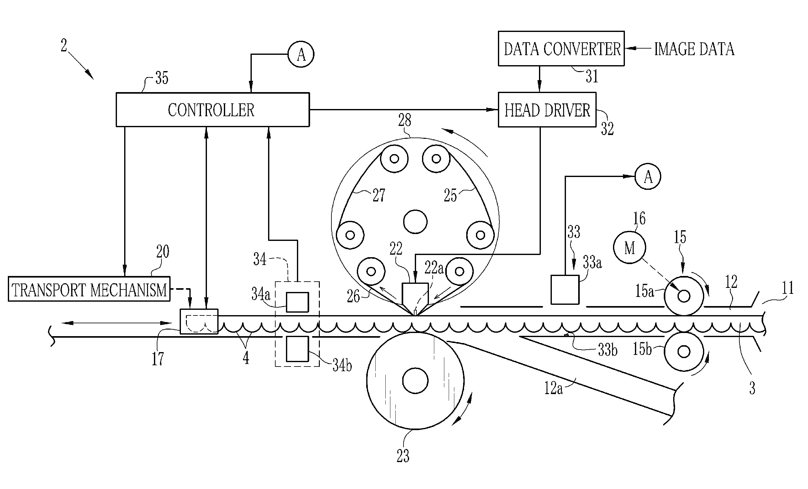
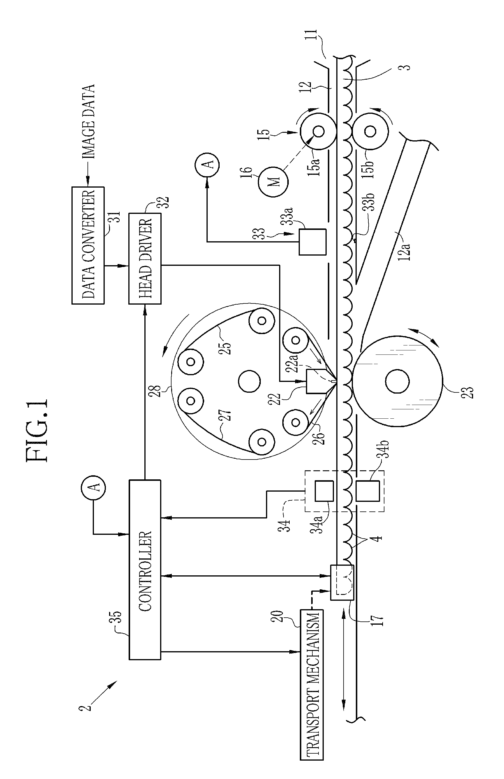
[0059]FIG. 1 illustrates an outline of a printer of the first embodiment of the present invention. A printer 2 records parallax images on the rear side of a lenticular sheet 3 with use of a sublimation method, for observing a stereo image. The printer 2 converts parallax images of two viewpoints into parallax images of six viewpoints, and records the parallax images of six viewpoints on the lenticular sheet 3.
[0060]As illustrated in FIG. 2, the lenticular sheet 3 has a plurality of lenticular lenses (hereinafter referred to as the lenses) 4 in the shape of a semicircular column arranged on the front side, and has a flat surface on the rear side. On the lenticular sheet 3, the lenses 4 extending in the direction of an arrow A (illustrated in FIG. 2) are arranged at a pitch of 100 LPI (Line Per Inch) in the direction of an arrow B (illustrated in FIG. 2, hereinafter referred to as the arrangement direction). Accordingly, the length of the lens 4 in the arrangement direction is approxi...
second embodiment
[0144]In a second embodiment, three lens sensors are used for detecting the oblique transportation angle of the lenticular sheet in addition to the lens pitch and the lens position. Note that since this embodiment is the same to the first embodiment except a part which is described below, the common components have same reference number and detailed explanations for the common components are omitted.
[0145]In FIGS. 17A and 17B, an arrangement of the lens sensors and a binary signal obtained from each lens sensor are illustrated. Note that to clarify a relation between the lens sensor and an intended lens for detection, the boundary 4a of the lens 4 is used as a specified place for explanation. Accordingly, in the illustration of FIGS. 17A and 17B, the rise point of the binary signal of the detection signal is corresponding to the boundary 4a of the lens 4. In practice, as the same as the first embodiment, the detection signal is divided into two values at a predetermined threshold va...
third embodiment
[0159]In a third embodiment, an angle of the reference line against the thermal head is measured with use of a function of the printer and is determined as a correction angle of the oblique transportation angle, so that the longitudinal direction of the lens is adjusted to coincide with the main-scanning direction with high accuracy. Although the printer having the construction illustrated in FIG. 15 is used as an example for following explanations, this embodiment can be applied to any other printers comprising the reference line and the oblique transportation sensor having at least two light receiving elements arranged in the main-scanning direction.
[0160]As illustrated in FIG. 21, the angle θ1 of the reference line 33b against the heater element array 22a of the thermal head 22 measured with use of the function of the printer 2. At first, a distance HA from a point PA on the reference line 33b to the heater element array 22a, and a distance HB from a point PB on the reference lin...
PUM
 Abstract
Description
Claims
Application Information
 - R&D
- Intellectual Property
- Life Sciences
- Materials
- Tech Scout
- Unparalleled Data Quality
- Higher Quality Content
- 60% Fewer Hallucinations
Browse by: Latest US Patents, China's latest patents, Technical Efficacy Thesaurus, Application Domain, Technology Topic, Popular Technical Reports.
© 2025 PatSnap. All rights reserved.Legal|Privacy policy|Modern Slavery Act Transparency Statement|Sitemap|About US| Contact US: help@patsnap.com


