Systems and methods of generating energy and fresh water from solar radiation

Inactive Publication Date: 2011-03-24
COMBINED POWER COOP
View PDF13 Cites 24 Cited by
  • Summary
  • Abstract
  • Description
  • Claims
  • Application Information

AI Technical Summary

Benefits of technology

[0012]In general terms, the present disclosure provides a solar reflector assembly useable for generating energy from solar radiation. Embodiments of the solar reflector assemblies are inflatable elongated tubes of flexible material with each tube including a reflective sheet to reflect solar radiation to a solar collector. This structure and the materials employed provide significant cost savings for manufacture, shipping and deployment of the solar reflector assemblies. The solar reflector assembly is configured to be deployed on a supporting body of liquid. This provides both liquid ballasting capability and structural support. Beneficially, the solar reflector assemblies are inexpensive to manufacture, deploy and operate, providing a cost effective solution for energy generation.
[0014]In exemplary embodiments, the reflective sheet can be configured to reflect substantially all solar radiation towards the solar collector. In another exemplary embodiment, the reflective sheet can be configured to substantially reflect a first prescribed wavelength range towards a solar collector and to substantially transmit a second prescribed wavelength range therethrough. In the case of an interior reflective sheet, the reflective sheet may also facilitate equilibrium of pressure on its opposing sides. One end cap assembly may be coupled to the elongated tube, or a pair of end cap assemblies can be coupled to the elongated tube, in which at least one of the end cap assemblies is configured to facilitate the flow of gas and / or liquid into and out of the elongated tube to maintain pressure within the tube. The upper portion formed of thin-gauge, flexible material allows solar radiation to pass through for reflection by the reflective sheet.
[0019]The reflective sheet may be coupled to the elongated tube in a manner to provide a pressure differential between opposing sides of the reflective sheet such that the reflective sheet can be given a prescribed shape to facilitate reflection of solar radiation towards the solar collector. The solar reflector assembly may facilitate equilibrium of pressure on opposing sides of the reflective, sheet. The lower ballast portion of the elongated tube contains liquid facilitating ballast. The liquid facilitating ballast has a top surface that is generally parallel to the surface of the supporting body of liquid. The system further includes a solar collector positioned to receive reflected solar radiation from the reflective sheet.
[0026]The elongated tube may further comprise a culture medium for photosynthetic biomass, thus forming a combined solar reflector and photobioreactor assembly (“CSP / PBR”). The culture medium housed in the tube can be used, e.g., to facilitate photosynthetic biomass growth, such as algal biomass. The reflective sheet may be configured to substantially reflect a first prescribed wavelength range towards a solar collector and to substantially transmit a second prescribed wavelength range therethrough to the culture medium within the elongated tube. In this manner, a portion of solar energy is directed towards the solar collector, while another portion is utilized by the culture medium, e.g., to facilitate photosynthetic biomass growth, such as algal biomass. The CSP / PBR assemblies may be disposed on a supporting body of liquid and include a solar collector positioned to receive reflected solar radiation from the reflective sheet. Beneficially, this embodiment serves to reduce the heat input, and therefore the cooling load for the biomass production component of such an embodiment
[0027]Exemplary embodiments include a combined solar reflector and desalination assembly comprising an inflatable elongated tube having an upper portion formed at least partially of flexible material and a lower ballast portion formed at least partially of flexible material, a reflective sheet coupled to a wall of the tube to reflect solar radiation, and at least one catchment device coupled to a wall of the tube. The elongated tube has an axis of rotation oriented generally parallel to a surface of a supporting body of liquid. The assembly may further comprise at least one end cap assembly coupled to the elongated tube to facilitate flow of gas and / or liquid into and out of the elongated tube. Exemplary embodiments of a combined solar reflector and desalination assembly may further comprise a pool housing a supporting body of liquid, and the assembly floats on the supporting body of liquid.

Problems solved by technology

Various approaches have been tried such as flash-distillation, reverse osmosis membranes, solar stills, among others, but none has produced water at high volumes and low cost.
However, current solar panel technology has been ineffective for large-scale uses, such as electrical generation sufficient for municipal applications.
The costs associated with such large-scale usages have been prohibitive.
Current solar panels are relatively expensive and do not allow cost-effective energy storage.
Although such CSP systems are better than traditional flat-panel photovoltaic cells for large-scale applications, shortfalls exist.
For example, glass and metal reflector assemblies are expensive to manufacture, ship and install.
Further, current tracking devices used with CSP can be relatively expensive and complicated.
As a result, current approaches have yet to achieve significant market penetration because of cost issues.
However, such systems can be expensive and, in many instances, cost prohibitive.
Both methods are energy and capital intensive, prohibiting wide spread adoption.

Method used


Image

  • Systems and methods of generating energy and fresh water from solar radiation
  • Systems and methods of generating energy and fresh water from solar radiation
  • Systems and methods of generating energy and fresh water from solar radiation

Examples


Embodiment Construction

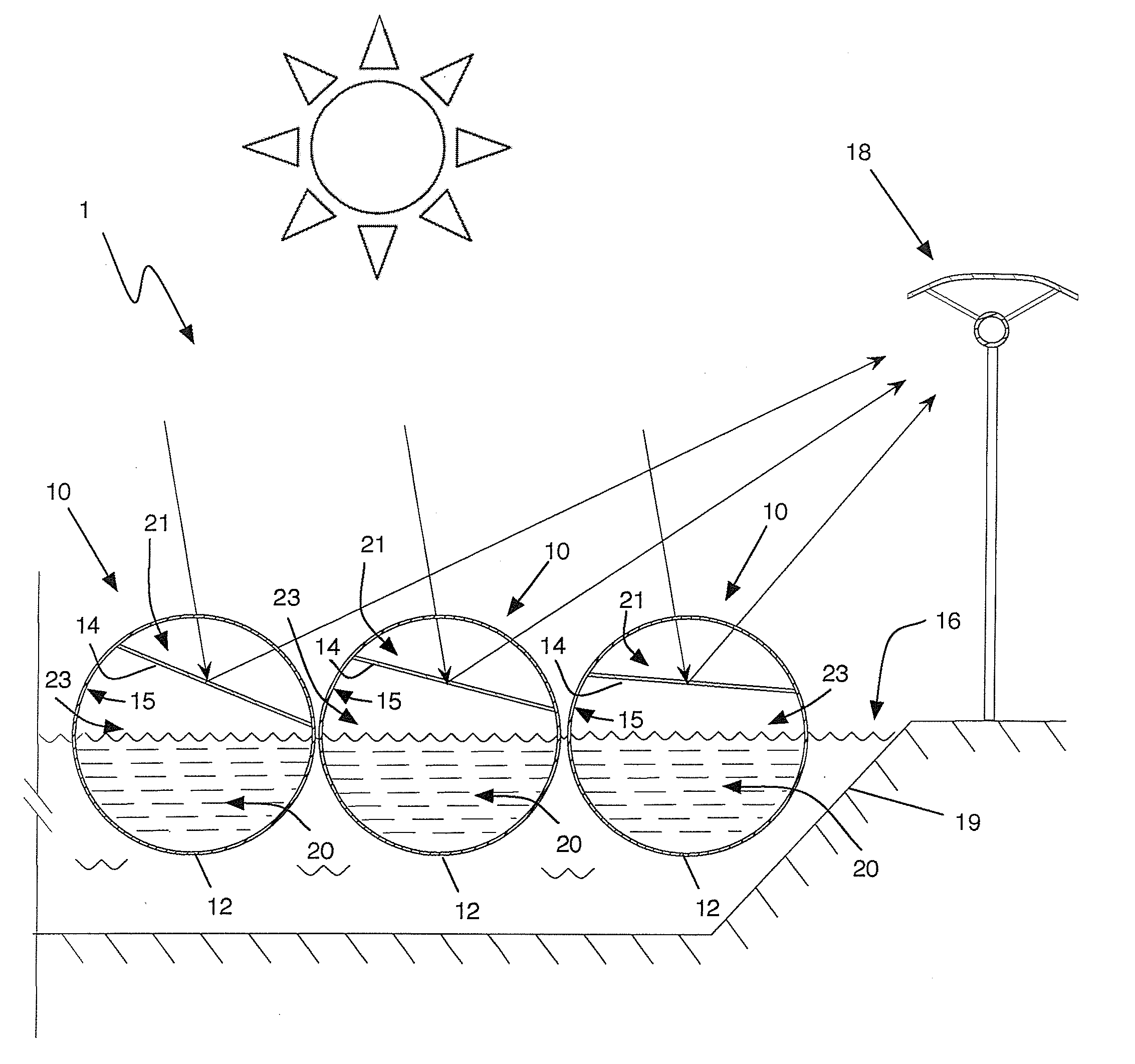
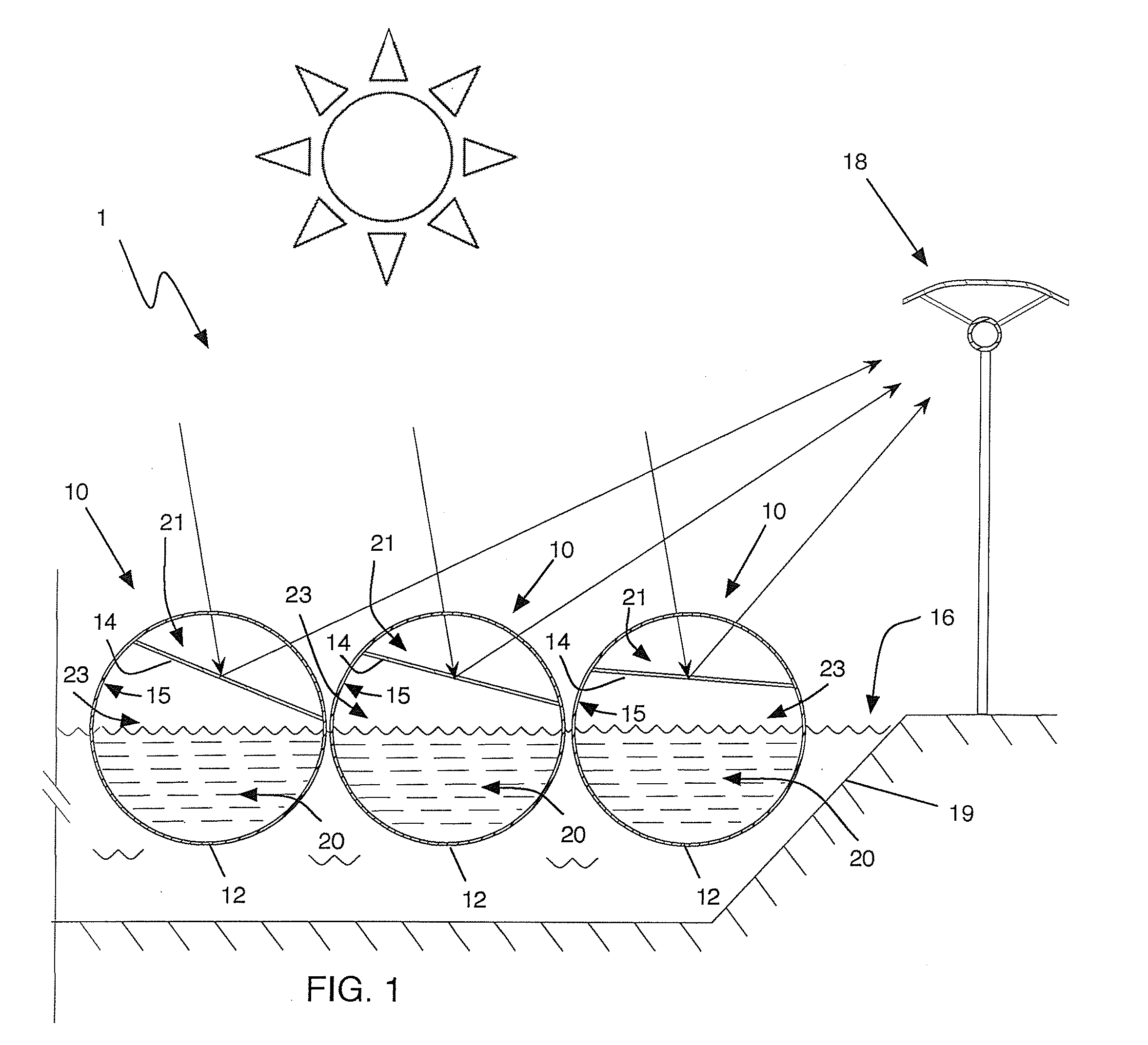
[0078]With reference now to the drawings, and particularly FIGS. 1 and 2, there is shown an array 1 of solar reflector assemblies 10. Each solar reflector includes an inflated elongated tube 12 having a reflective sheet 14 coupled along opposed sides of the sheet to a wall of the tube. In exemplary embodiments, reflective sheet 14 is coupled to an interior wall 15 of the elongated tube 12 so that the reflective sheet 14 divides the elongated tube 12 into two portions, an upper portion or chamber 21 and a lower ballast portion or chamber 23.

[0079]More particularly, in exemplary embodiments the elongated tube 12 is a unitary structure that includes lower ballast portion 23, which provides ballast for the solar reflector assembly 10. In other words, lower ballast portion 23 is the lower section of the elongated tube itself and, as such, is integrally formed with the elongated tube 12. This structure is advantageous because it obviates the need for additional components or structural el...


PUM


Abstract

A combined solar reflector and desalination assembly is provided for generating energy and fresh water from solar radiation. The solar reflector assembly is configured to be deployed on a supporting body of liquid and to reflect solar radiation to a solar collector. A combined solar reflector and desalination assembly comprises an inflatable elongated tube having an upper portion formed at least partially of flexible material and a lower ballast portion formed at least partially of flexible material. A reflective sheet is coupled to a wall of the tube to reflect solar radiation. At least one catchment device and collection assembly are coupled to the tube. The elongated tube may have an axis of rotation oriented generally parallel to a surface of a supporting body of liquid.

Description

CROSS-REFERENCE TO RELATED APPLICATIONS[0001]This application is a continuation-in-part of U.S. patent application Ser. No. 12 / 849,761, filed Aug. 3, 2010, which is incorporated by reference herein in its entirety and which claims priority to U.S. Patent Application Ser. Nos. 61 / 231,081, filed Aug. 4, 2009, 61 / 233,667, filed Aug. 13, 2009, and 61 / 244,349, filed Sep. 21, 2009, each of which is incorporated by reference herein in its entirety.FIELD OF THE DISCLOSURE[0002]The present disclosure relates to solar energy systems.BACKGROUND OF THE DISCLOSURE[0003]There has been a long-standing need to provide energy generation from renewable sources. Various renewable energy sources have been pursued, such as solar energy, wind, geothermal, and biomass for biofuels as well as others. There also exists an ever-increasing need for cost effective fresh water production systems to keep pace with the fresh water needs of an ever-increasing population. Various approaches have been tried such as ...

Claims


Application Information

Patent Timeline
IPC IPC(8): F24J2/36C02F1/14B01D3/00B01D3/04C12M1/24F24S10/70F24S23/70
CPCF24J2/0015F24J2/1052F24J2/1057F24J2/16F24J2/242Y02E10/47F24J2/5267F24J2/5271F24J2/541Y02E10/44F24J2/243F24S10/72F24S10/73F24S20/25F24S20/70F24S20/80F24S23/77F24S23/81F24S23/82F24S30/20F24S30/425Y02A20/142Y02E10/40
Inventor KING, JOHN D.H.KRAMER, NICHOLAS A.
Owner COMBINED POWER COOP
Why Eureka
Try Eureka