
Display device

a display device and display technology, applied in the field of display devices, can solve the problems of difficult detection of simultaneously contacted two points, inability to detect input coordinates, and hardly occuring capacitance change of electrodes, and achieve the effect of high accuracy and good accuracy

Inactive Publication Date: 2011-03-24
PANASONIC LIQUID CRYSTAL DISPLAY CO LTD +1
View PDF12 Cites 86 Cited by
  • Summary
  • Abstract
  • Description
  • Claims
  • Application Information

AI Technical Summary

Benefits of technology

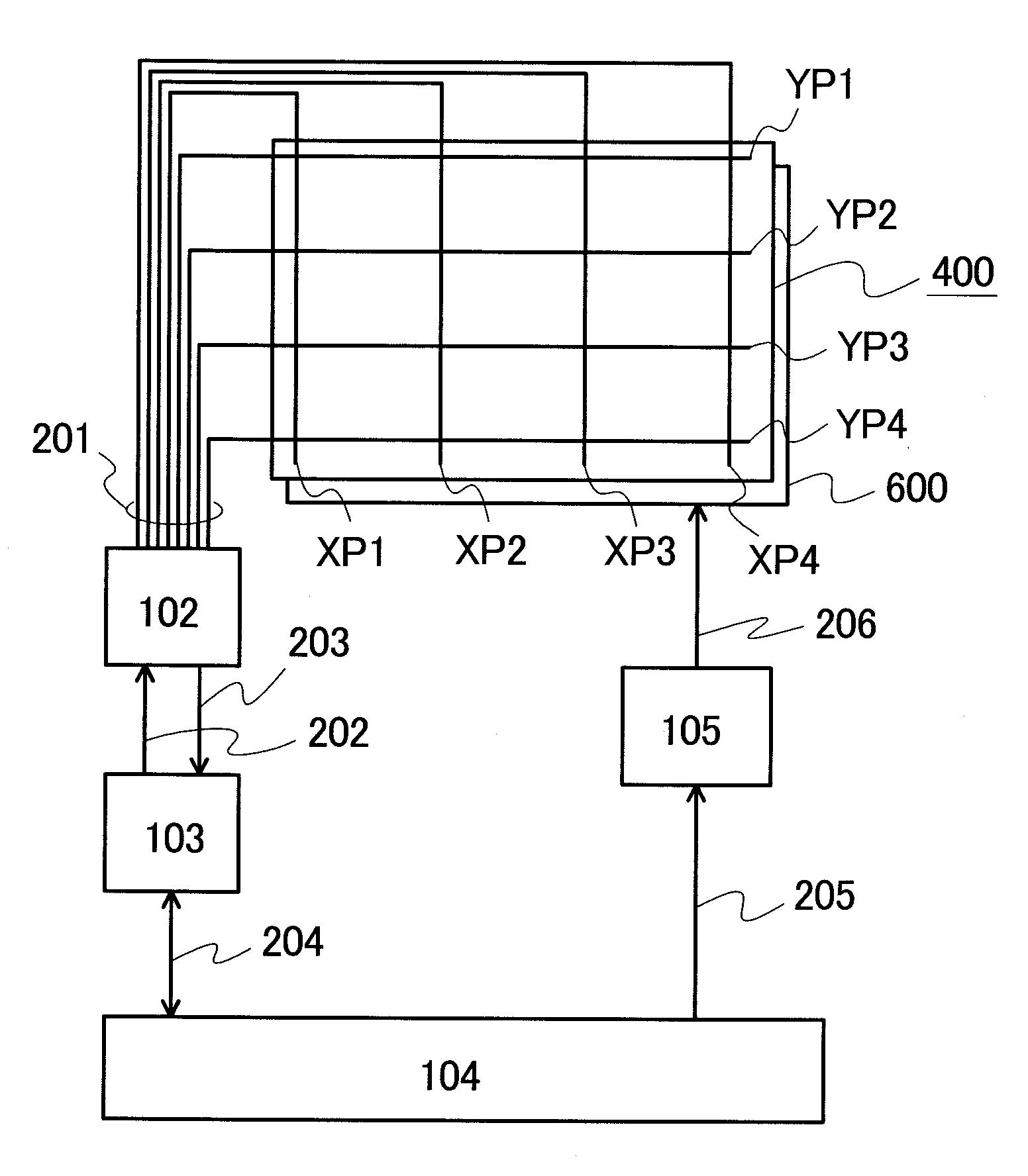
[0010]The invention has been made for solving the problems in the related art, and it is an object of the invention to provide a technique which enables, in a display device including a capacitive coupling touch panel, reaction to touch with nonconductive input means, realization of highly accurate position detection with a small number of electrodes even with a small touch area, and detection of coordinates with good accuracy when contacted simultaneously at two points.

Problems solved by technology

Therefore, when a resin-made stylus or the like having no conductivity used in the resistive film system and the like is brought into contact with the capacitive touch panel, the capacitance change of the electrode hardly occurs, and therefore, a problem results in that input coordinates cannot be detected.
Moreover, in the use of the capacitive touch panel where a resin-made stylus or the like contacts simultaneously at two points, since two X-coordinates and two Y-coordinates are detected, four coordinates are conceivable as potential contact points, which makes it difficult to detect the simultaneously contacted two points.

Method used


Image

  • Display device
  • Display device
  • Display device

Examples


Embodiment Construction

[0072]A typical outline of the invention disclosed herein will be briefly described below.

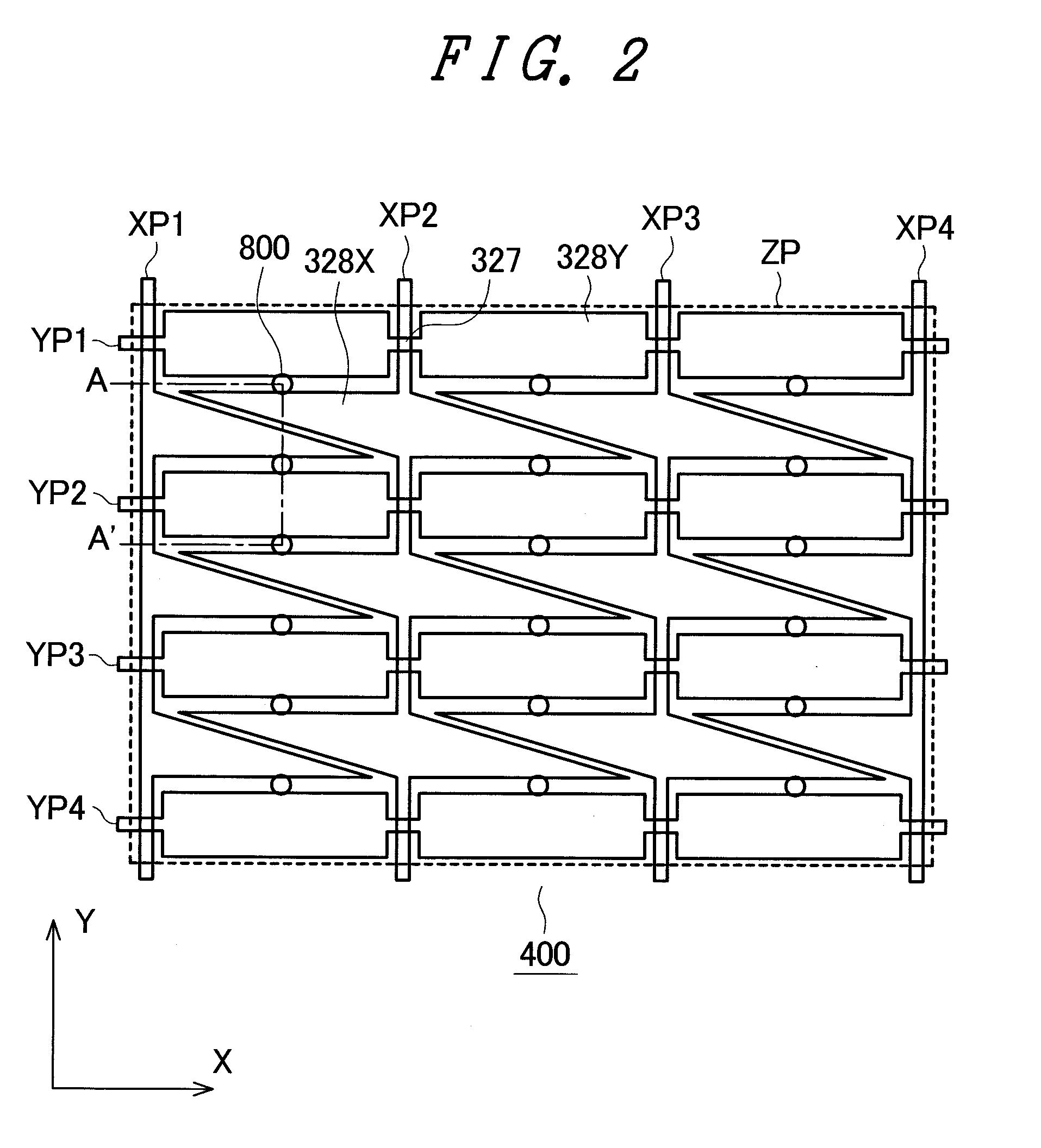
[0073]In the invention, for solving the above problems, a capacitive touch panel including a plurality of X-electrodes, a plurality of Y-electrodes, and a Z-electrode overlapping both the X-electrode and the Y-electrode is used. In the capacitive touch panel, the X-electrode and the Y-electrode intersect with each other via a first insulating layer; each of the X-electrode and the Y-electrode is formed such that pad portions and fine line portions are alternately arranged in its extending direction; and the pad portion of the X-electrode and the pad portion of the Y-electrode are arranged so as not to overlap each other as viewed in plan.

[0074]The Z-electrode is formed so as to overlap, via a second insulating layer, both the X-electrode and the Y-electrode neighboring to each other as viewed in plan. A spacer is disposed between the Z-electrode, and the X-electrode and the Y-electrode, and the...


PUM


Abstract

In a display device including a capacitive coupling touch panel, reaction to touch with nonconductive input means is achieved, and highly accurate position detection is realized with a small number of electrodes even with a small touch area. X-electrodes and Y-electrodes which intersect with each other via a first insulating layer and a Z-electrode which is in a floating state via a second insulating layer are disposed. For the Z-electrode, a material whose thickness changes by pressing due to touch, such as an elastic conductive material, is used. The Z-electrode is arranged so as to overlap both the X-electrode and the Y-electrode neighboring to each other. A pad portion of the X-electrode has a shape such that an area is maximized in the vicinity of a fine line portion of the relevant X-electrode.

Description

CROSS-REFERENCE TO RELATED APPLICATION[0001]The present application claims priority from Japanese application JP 2009-216798 filed on Sep. 18, 2009, the content of which is hereby incorporated by reference into this application.BACKGROUND OF THE INVENTION[0002]1. Field of the Invention[0003]The present invention relates to an input device which inputs coordinates by touching a screen and a display device including the input device, and in particular, the invention is suitable for increasing coordinate detection accuracy in a display device having a capacitive touch panel.[0004]2. Description of the Related Art[0005]Display devices including a device (hereinafter also referred to as a touch sensor or a touch panel) which inputs information by a touch operation (contacting and pressing operation; hereinafter simply referred to as touch) on a display screen using a user's finger, a pen, or the like are used for mobile electronic apparatuses such as PDAs or portable terminals, various h...

Claims


Application Information

Patent Timeline
IPC IPC(8): G06F3/045
CPCG06F3/044G06F3/03545G06F3/0447G06F3/0445G06F3/0446
Inventor ANNO, KOUICHI
Owner PANASONIC LIQUID CRYSTAL DISPLAY CO LTD
Learn More