
System and Method for Non-Linear Dimming of a Light Source

a non-linear dimming and light source technology, applied in the field of semiconductor circuits, can solve the problems of high resource demands both, high system and circuit complexity of the circuit required to support time variable lighting control, and high resource requirements of the microcontroller, and achieve the effects of high resource demands both, and high system and circuit complexity

Active Publication Date: 2011-03-24
INFINEON TECH AUSTRIA AG
View PDF3 Cites 38 Cited by
  • Summary
  • Abstract
  • Description
  • Claims
  • Application Information

AI Technical Summary

Benefits of technology

[0007]The foregoing has outlined, rather broadly, features of the present invention. Additional features of the invention will be described, hereinafter, which form the subject of the claims of the invention. It should be appreciated by those skilled in the art that the conception and specific embodiment disclosed may be readily utilized as a basis for modifying or designing other structures or processes for carrying out the same purposes of the present invention. It should also be realized by those skilled in the art that such equivalent constructions do not depart from the spirit and scope of the invention as set forth in the appended claims.

Problems solved by technology

As the requirements for lighting systems have become more sophisticated, however, the circuitry required to support time variable lighting control has required high system and circuit complexity, precise analog components, and high resource demands both in terms of circuit board area and the number of required electronic components.
While a microcontroller can be used to generate independent pulse modulated signals to vary the intensity of each light, the disadvantage of such an approach is that microcontrollers typically have a limited number of available hardware resources such as timers, interrupt lines, and general purpose I / O pins.
The use of software and CPU resources to track and control dimming profiles of multiple lights leaves fewer resources available to other automotive applications such as power train and safety systems.

Method used


Image

  • System and Method for Non-Linear Dimming of a Light Source
  • System and Method for Non-Linear Dimming of a Light Source
  • System and Method for Non-Linear Dimming of a Light Source

Examples


Embodiment Construction

[0024]The making and using of embodiments are discussed in detail below. It should be appreciated, however, that the present invention provides many applicable inventive concepts that may be embodied in a wide variety of specific contexts. The specific embodiments discussed are merely illustrative of specific ways to make and use the invention, and do not limit the scope of the invention.

[0025]The present invention will be described with respect to embodiments in a specific context, namely a light-dimming engine. Embodiments of this invention may also be applied to other circuits and systems that require non-linear control of time varying signals.

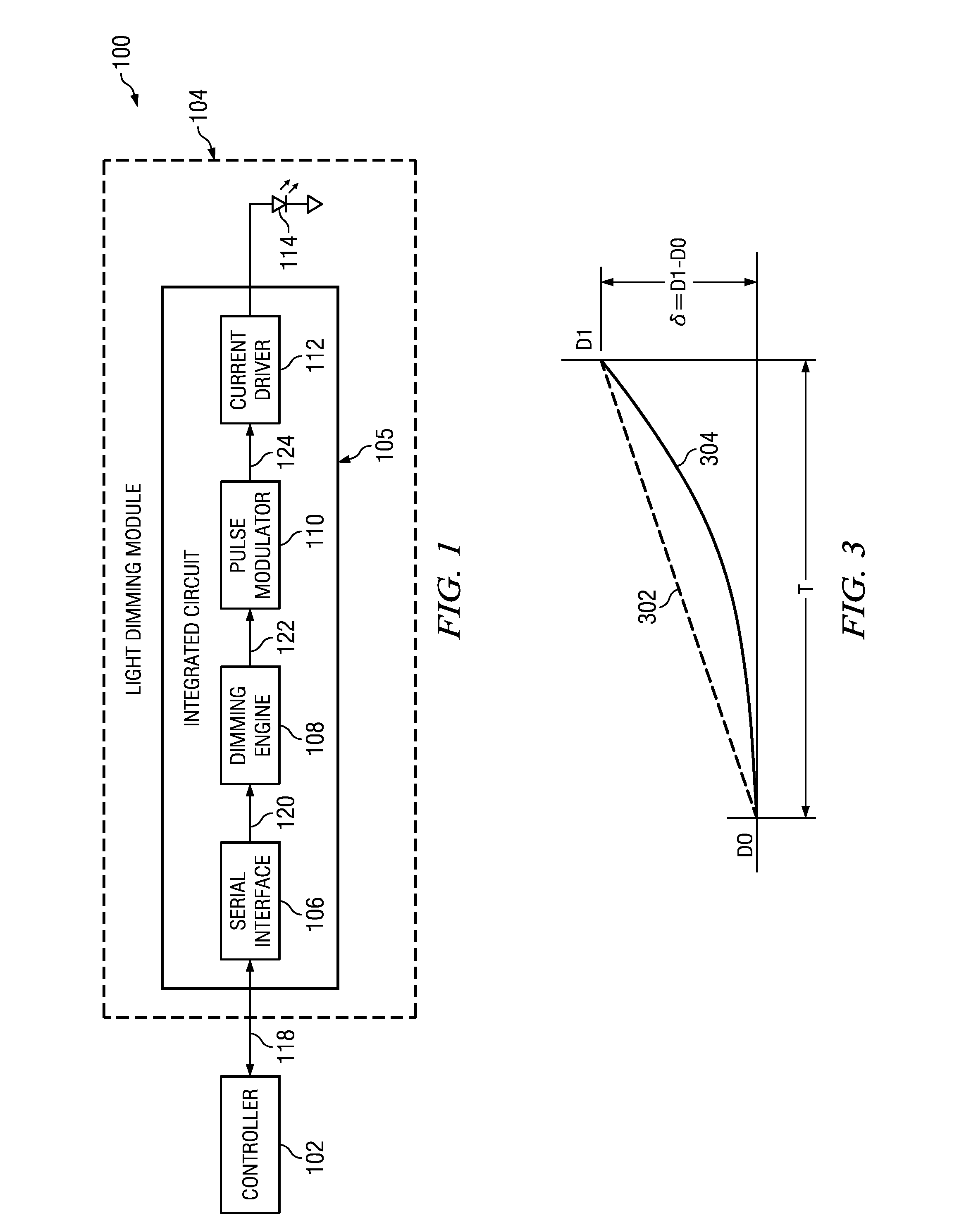
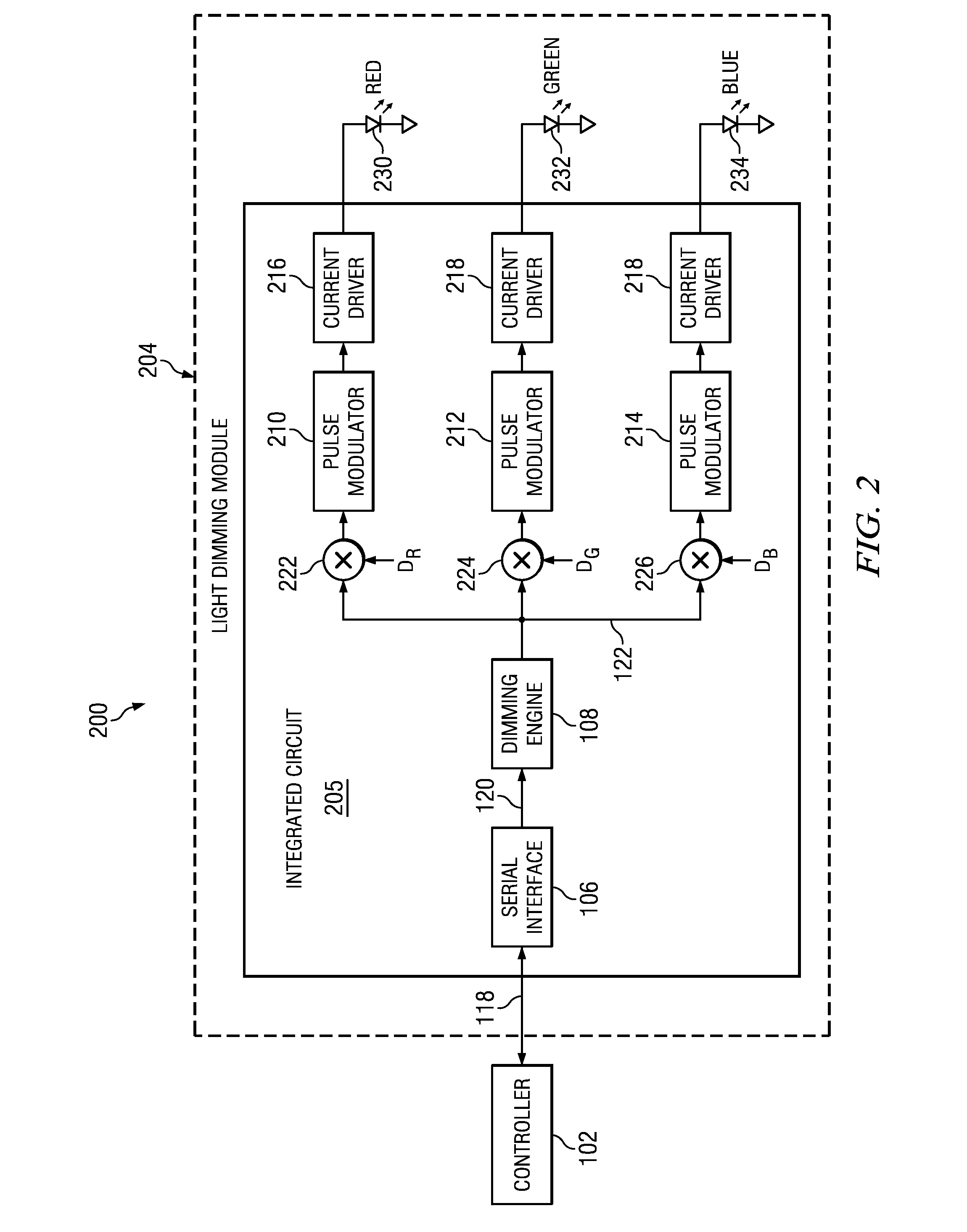
[0026]An automotive light control system 100 according to an embodiment of the present invention is illustrated in FIG. 1. Controller 102 is coupled to light dimming module 104 that controls the illumination level of light emitting diode (LED) 114. Light dimming module 104 has serial interface 106, dimming engine 108, pulse modulator 110 an...


PUM


Abstract

In one embodiment, a light dimming module is disclosed. The light dimming module has a dimming engine coupled to a digital input interface and an output interface. The dimming engine is configured to provide a N-segment piecewise linear exponential digital control signal, and the output interface is configured to control the intensity of a light source.

Description

CROSS REFERENCE TO RELATED APPLICATIONS[0001]This application relates to the following co-pending and commonly assigned EPO patent application: Application number EP09155019.4, filed Mar. 12, 2009, entitled “Sigma Delta Current Source and LED Driver,” which application is hereby incorporated herein by reference.TECHNICAL FIELD[0002]This invention relates generally to semiconductor circuits, and more particularly to a system and method for non-linear dimming of a light source.BACKGROUND[0003]In places that require variable illumination, such as homes, theaters, auditoriums, and the interiors of automobiles, it is desirable to gradually change the level of illumination in order for the human eye to comfortably adapt to changes in light intensity. Such a change in illumination is achievable via electronic and computer control, from computer controlled interior lighting systems to simple light dimmer circuits.[0004]As the requirements for lighting systems have become more sophisticated,...

Claims


Application Information

Patent Timeline
IPC IPC(8): H05B37/02G06G7/24
CPCH05B33/0818H05B33/086H05B33/0857H05B45/20H05B45/10
Inventor SCENINI, ANDREALOGIUDICE, ANDREAFILIPPO, ROBERTOMUNARI, DIEGO GAETANOTOSATO, FEDERICO
Owner INFINEON TECH AUSTRIA AG
Learn More