
Attack packet detecting apparatus, attack packet detecting method, video receiving apparatus, content recording apparatus, and IP communication apparatus

a packet detection and packet technology, applied in the field of attack packet detecting apparatuses and attack packet detecting methods, can solve the problems of reducing processing efficiency, unable to provide services and systems, and placing high loads on network devices, so as to efficiently defend attacks and efficiently classify packets

Inactive Publication Date: 2011-03-17
PANASONIC CORP
View PDF9 Cites 19 Cited by
  • Summary
  • Abstract
  • Description
  • Claims
  • Application Information

AI Technical Summary

Benefits of technology

[0048]The present invention makes it possible, upon detection of an attack in which a large number of packets is transmitted, to update attack packet information for identifying attack packets, using information obtained from the received packets. For this reason, it is possible to efficiently and accurately classify packets into packets that should be discarded and packets that should be transferred to the main memory.
[0049]In this way, the present invention provides attack packet detecting apparatuses and attack packet detecting methods and the like for efficiently defending attacks by transmission of large amounts of packets.CROSS-REFERENCE TO RELATED APPLICATION
[0050]This application claims the benefit of Japanese Patent Application No. 2008-130061, filed on May 16, 2008. All the disclosures of the above application including the Description, drawings, and Claims are incorporated herein by reference.

Problems solved by technology

Conventionally existing DoS attacks disable services and systems by transmitting large amounts of data in short time to network devices having network functions and thereby placing high loads on the network devices.
This method enables the devices to preferentially process packets that should be processed, which reduces decrease in processing efficiency due to DoS attacks.

Method used


Image

  • Attack packet detecting apparatus, attack packet detecting method, video receiving apparatus, content recording apparatus, and IP communication apparatus
  • Attack packet detecting apparatus, attack packet detecting method, video receiving apparatus, content recording apparatus, and IP communication apparatus
  • Attack packet detecting apparatus, attack packet detecting method, video receiving apparatus, content recording apparatus, and IP communication apparatus

Examples


embodiment 1

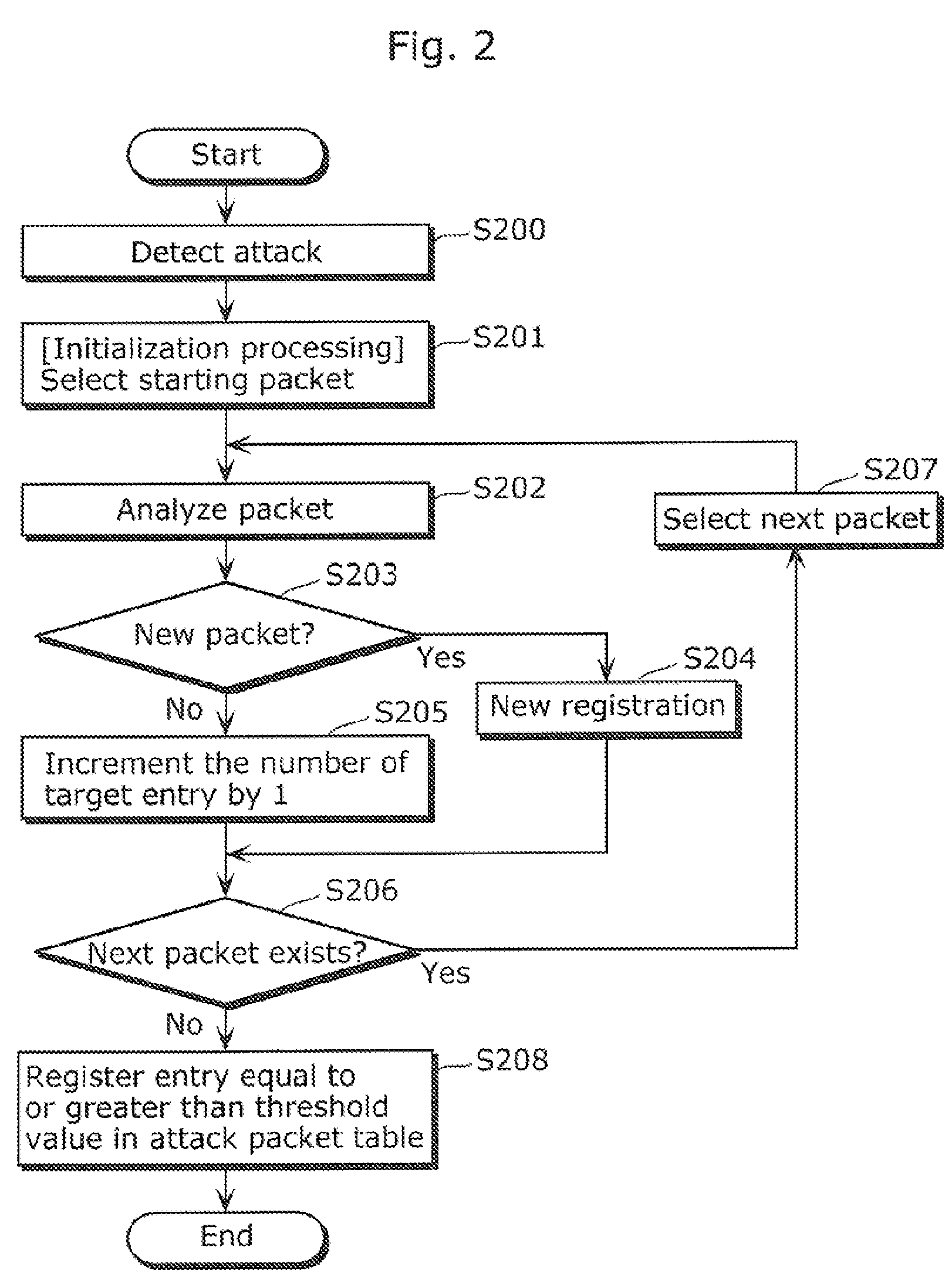
[0064]Embodiment 1 is described with reference to FIG. 1 to FIG. 4.

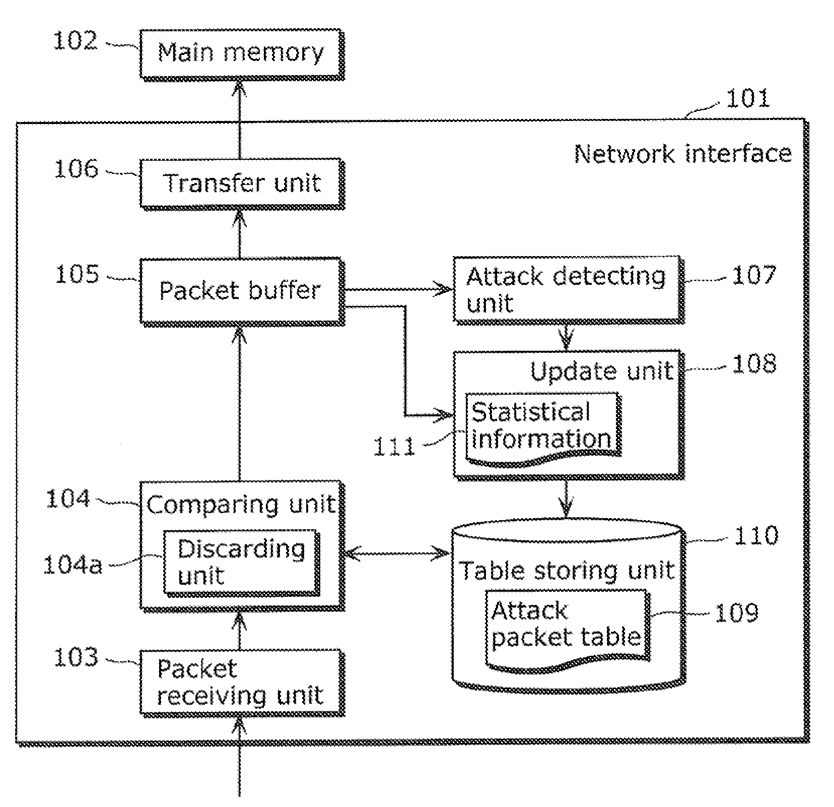
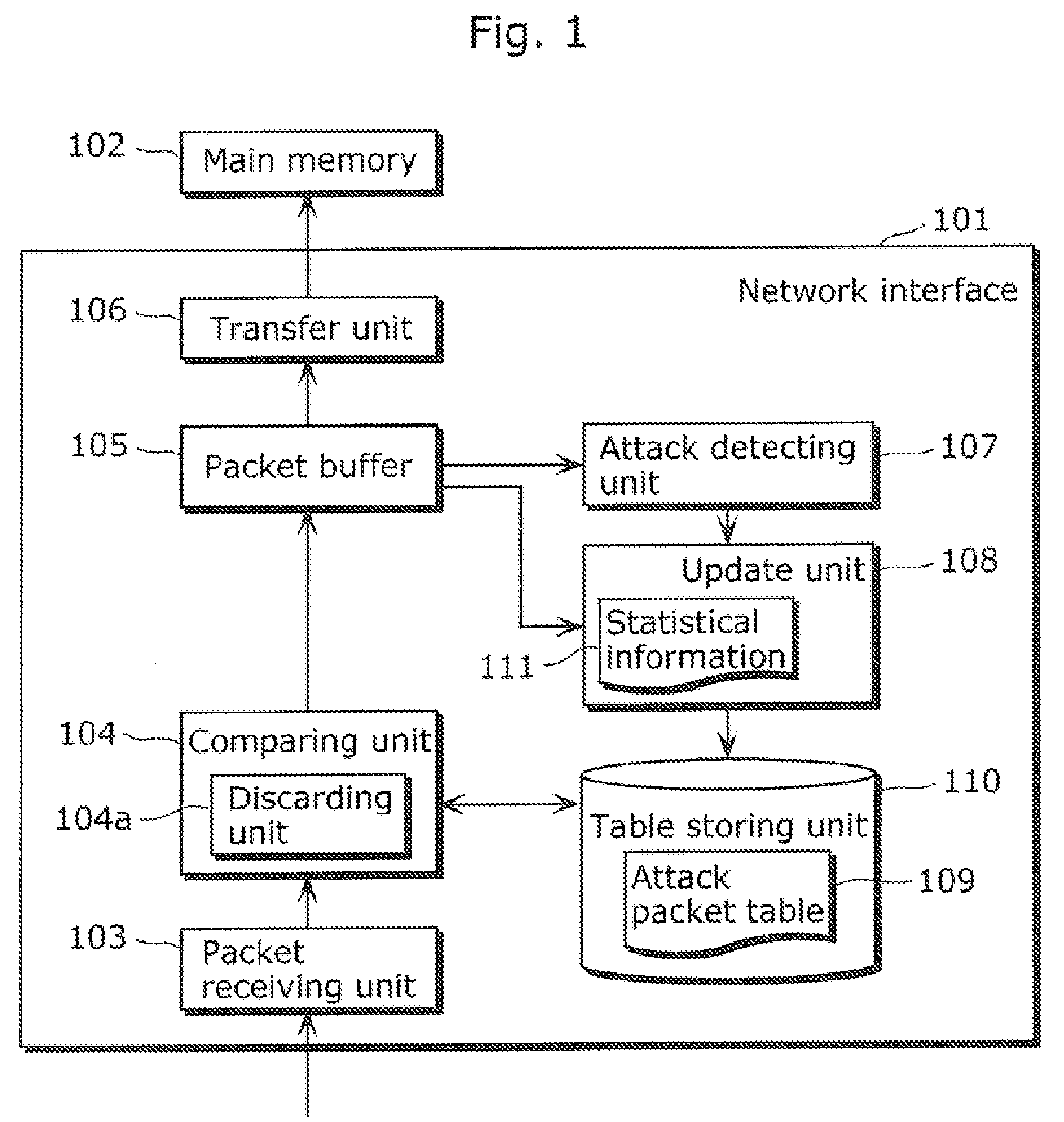
[0065]FIG. 1 is a block diagram showing a structure of a network interface 101 in Embodiment 1.

[0066]The network interface 101 is an example of an attack packet detecting apparatus according to the present invention.

[0067]The network interface 101 includes a packet buffer 105 for accumulating packets received, and transfers the packets accumulated in the packet buffer 105 to a main memory 102.

[0068]The main memory 102 is a recording media such as a DRAM (Dynamic Random Access Memory) included in a network apparatus with the network interface 101. The network apparatus performs processing such as reading packets from the main memory 102 and rearranging the packets.

[0069]The attack packet detecting apparatus according to the present invention may further include the main memory 102. In this case, the network apparatus provided with the attack packet detecting apparatus reads packets from the main memory 102 included in...

embodiment 2

[0166]Next, Embodiment 2 is described with reference to FIGS. 6, 7, and 8.

[0167]FIG. 6 is a block diagram showing a structure of a network interface 201 in Embodiment 2.

[0168]The network interface 201 in Embodiment 2 is another example of an attack packet detecting apparatus according to the present invention. As shown In FIG. 6, the network interface 201 has approximately the same structure as that of the network interface 101 in Embodiment 1 as shown in FIG. 1.

[0169]However, the network interface 201 in Embodiment 2 is different from the network interface 101 in Embodiment 1 in that the network interface 201 pre-registers possible attack patterns in an attack packet table 209, validates one of the registered attack patterns that corresponds to a DoS attack detected, and discards received packets corresponding to the attack pattern.

[0170]More specifically, a table storing unit 110 has recorded therein an attack packet table 209 in which possible attack patterns are pre-registered.

[...

embodiment 3

[0205]Next, Embodiment 3 is described with reference to FIG. 9.

[0206]A network interface 301 in Embodiment 3 is intended to perform, in a higher application layer, processing performed by the update unit 108 that uses hardware in the network interface 101 in Embodiment 1.

[0207]More specifically, in Embodiment 3, the processing such as update of an attack packet table 109 by the update unit 108 is performed by a CPU 302 of a network apparatus provided with the network interface 301.

[0208]In this embodiment, the attack packet detecting apparatus is configured with at least the network Interface 301 and the CPU 302.

[0209]FIG. 9 is a block diagram showing a structure of a network interface 301 in Embodiment 3.

[0210]The network Interface 301 includes a packet buffer 105 for accumulating packets received, and transfers the packets accumulated in the packet buffer 105 to a main memory 102.

[0211]The network interface 301 includes: a packet receiving unit 103; a comparing unit 104; a packet ...


PUM


Abstract

A network interface (101) includes: a packet receiving unit (103); a packet buffer (105); and a transfer unit (106) which transfers packets accumulated in the packet buffer to a main memory (102), and further including: an attack detecting unit (107) which detects an attack in which a large number of packets is transmitted, based on an accumulated amount of packets in the packet buffer (105); a table storing unit (110) for storing an attack packet table (109) in which attack packet identification information is registered; an update unit (108) which updates the attack packet table (109), using information obtained from the packets accumulated in the packet buffer; and a discarding unit (104a) which discards the packets received by the packet receiving unit (103) when the packets correspond to the updated attack packet information, before the packets are transferred to the main memory.

Description

TECHNICAL FIELD [0001]The present invention relates to attack packet detecting apparatuses and attack packet detecting methods for detecting high-load attacks, such as DoS (Denial of Service) attacks, against communication systems.BACKGROUND ART [0002]Conventionally existing DoS attacks disable services and systems by transmitting large amounts of data in short time to network devices having network functions and thereby placing high loads on the network devices.[0003]A well-known attack method in the DoS attack is transmitting a numerous number of ICMP Echo Request packets in short time, using a protocol called ICMP (Internet Control Message Protocol). Conventionally, knowledge of network has been required to perform such DoS attacks.[0004]However, recent years have seen a widespread use of easily available tools for DoS attacks. This makes environments where even a user having little knowledge of network can easily perform such attacks.[0005]For this reason, some methods of preven...

Claims


Application Information

Patent Timeline
IPC IPC(8): G06F11/30
CPCG06F2213/3808G06F13/385
Inventor EBINA, AKIHIROTSUJI, ATSUHIRO
Owner PANASONIC CORP
Learn More