
Compression type coaxial cable F-connectors with traveling seal and barbless post

a coaxial cable and f-connector technology, applied in the field of electric connectors, can solve the problems of limited maximum displacement response to compression, and achieve the effects of high operating bandwidth, reliable internal seals, and quick and reliable connection

Inactive Publication Date: 2011-03-17
PERFECTVISION MFG
View PDF102 Cites 40 Cited by
  • Summary
  • Abstract
  • Description
  • Claims
  • Application Information

AI Technical Summary

Benefits of technology

"The present invention provides improved, axial compression type F-connectors that can be quickly and reliably connected to coaxial cables of varying diameters and structures. The new F-connectors establish a high operating bandwidth and create reliable internal seals. The end cap has a smooth, frictionally gripping surface that can be positioned at any point along the shank. The connector has a rigid, metallic hex-headed nut for threaded sockets and an elongated, preferably molded plastic body. The connector can be easily and safely installed without deformation of critical parts during final compression. The invention also includes an improved sealing grommet for enhancing the required weatherproof and moisture resistant characteristics of the fitting. The F-connector can be used with a variety of different installation tools and cables. The connector is designed to reliably provide a good electrical connection path between the threaded nut, the internal post, and the coaxial cable to which it is fitted. The connector is also adaptable for use in wideband RF applications and can be safely and properly installed without deformation of critical parts during final compression."

Problems solved by technology

However, maximum displacement in response to compression is limited by the integral stop ring axially adjoining the shank.

Method used


Image

  • Compression type coaxial cable F-connectors with traveling seal and barbless post
  • Compression type coaxial cable F-connectors with traveling seal and barbless post
  • Compression type coaxial cable F-connectors with traveling seal and barbless post

Examples


Embodiment Construction

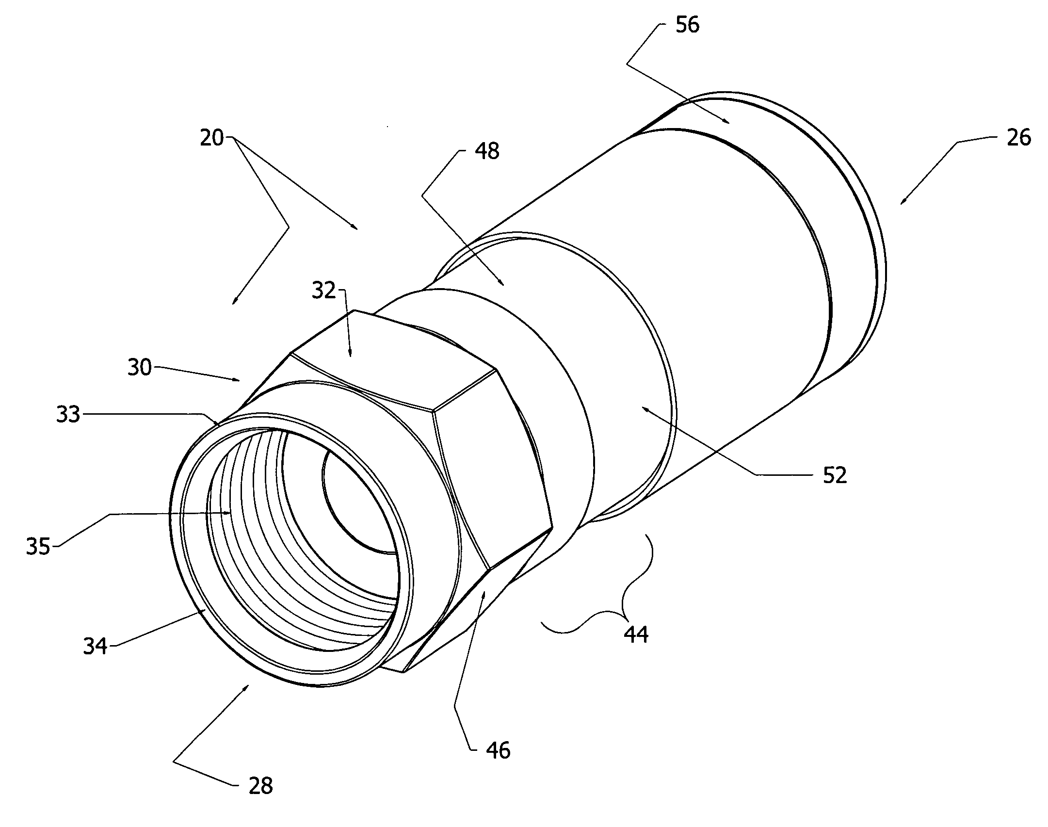
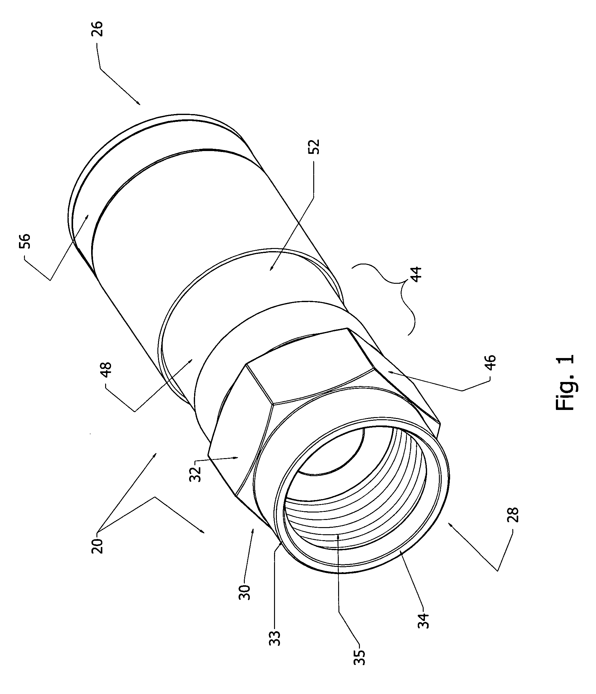
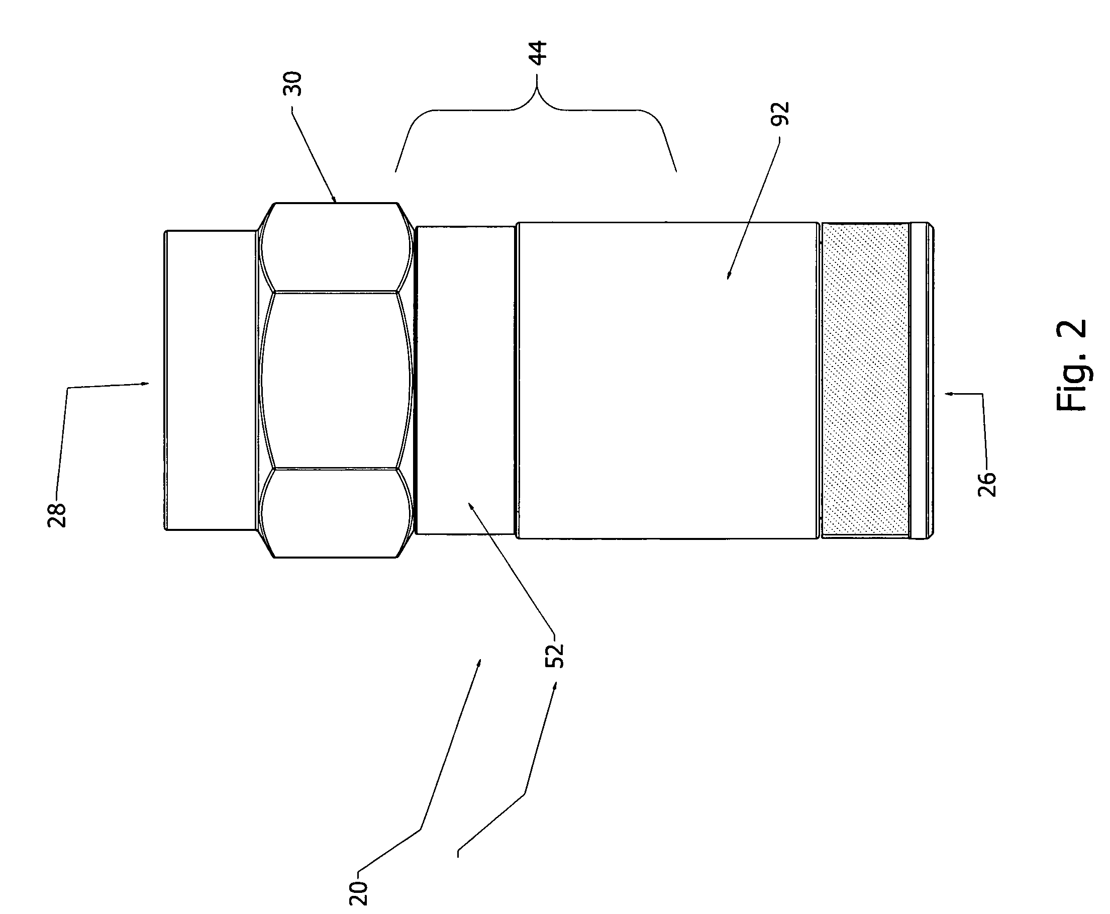
[0080]With initial reference directed to FIGS. 1-5 of the appended drawings, an open F-connector for coaxial cable constructed generally in accordance with the best mode of the invention has been generally designated by the reference numeral 20. The same connector disposed in a closed position is designated 21 (i.e., FIGS. 6-8). Connectors 20 and 21 are adapted to terminate an end of properly prepared coaxial cable, the proper preparation of which is well recognized by installers and others with skill in the art. After a prepared end of coaxial cable is properly inserted through the open bottom end 26 (FIG. 1) of an open connector 20, the connector is placed within a suitable compression hand tool for compression, substantially assuming the closed configuration of FIG. 6.

[0081]With additional reference directed toFIGS. 11 and 13, the preferred rigid, tubular, metallic nut 30 has a conventional faceted, preferably hexagonal drive head 32 integral with a protruding, coaxial stem 33. C...


PUM


Abstract

Axially compressible, self-sealing, high bandwidth F-connectors for conventional hand tools for interconnection with coaxial cable. An internal, dual segment sealing grommet activated by compression elongates and deforms to provide a travelling seal. Each connector has a rigid nut that is rotatably secured to a, tubular body. A rigid, conductive post has a barbless shank that coaxially extends through the connector and penetrates the coaxial cable within the connector. A tubular, metallic end cap is slidably fitted to a body shank, and is thereafter forcibly compressed lengthwise during installation. The end cap has a ring groove for seating the enhanced grommet. The end cap can irreversibly assume any position, being held by end cap teeth. The grommet travels and extrudes during compression to mate and intermingle with a portion of the cable braid that is looped back to form a prepared cable end.

Description

CROSS REFERENCE TO RELATED APPLICATION[0001]This is a Continuation-in-Part application based upon a prior U.S. utility patent application entitled “Sealed Compression Type Coaxial Cable F-Connectors,” filed Feb. 26, 2009, Ser. No. 12 / 380,327, which was a Continuation-in-Part of an application entitled “Compression Type Coaxial Cable F-Connectors,” Ser. No. 12 / 002,261, filed Dec. 17, 2007, now U.S. Pat. No. 7,513,795, issued Apr. 7, 2009.BACKGROUND OF THE INVENTION[0002]1. Field of the Invention[0003]The present invention relates generally to electrical connectors for coaxial cables and related electrical fittings. More particularly, the present invention relates to coaxial F-connectors of the axial compression type which are adapted to be installed with hand compression tools, and specifically to F connectors that are internally sealed when compressed. Known prior art of relevance is classified in U. S. patent No. Class 439, Subclasses 349, 583, and 584.[0004]2. Description of the R...

Claims


Application Information

Patent Timeline
Patent Type & Authority Applications(United States)
IPC IPC(8): H01R9/05
CPCH01R9/0524H01R2101/00H01R13/5205
Inventor SHAW, GLEN DAVIDCHASTAIN, ROBERT J.
Owner PERFECTVISION MFG
Learn More